Ultrasonic probe

Inactive Publication Date: 2001-09-13
KONICA MINOLTA INC
View PDF0 Cites 56 Cited by
  • Summary
  • Abstract
  • Description
  • Claims
  • Application Information

AI Technical Summary

Benefits of technology

0018] The present invention has been made to solve the problems of the conventional system described above. The object of the present invention is to provide a high-quality ultrasonic probe which has the acoustic impedance substantially equal to that of the acoustic matchi

Problems solved by technology

Accordingly, there occurs a problem that the efficiency in transmitting and receiving the ultrasonic wave is reduced and further the frequency characteristic is degraded.
Further, there is another problem that an insulator of a signal electrical terminal disposed between the piezoelectric element and the backing material is generally thick, which has a negative effect on the damping of the backing material and degrades the acoustic characteristic of the ultrasonic probe, especially the frequency characteristic thereof.
This problem is also seen at the positive electrode side conductive layer.
Further, when the electrical impedance on the electrical conductive path is increased, the capability of removing external electrical noise is deteriorated, and accordingly the external electromagnetic noise causes the diagnosis image to be deteriorated, which makes the simultaneous optimization of an acoustic matching condition and an electrical conductive path more difficult, and prevents an accurate diagnosis based on the ultrasonic image, and eventually might occur a serious problem of inducing a wrong diagnosis.
Further, in the conventional system, since the electrodes are disposed on respective end faces of the piezoelectric element with respect to the short axis direction thereof and are extended out therefrom, if the piezo

Method used


Image

  • Ultrasonic probe
  • Ultrasonic probe
  • Ultrasonic probe

Examples


first embodiment

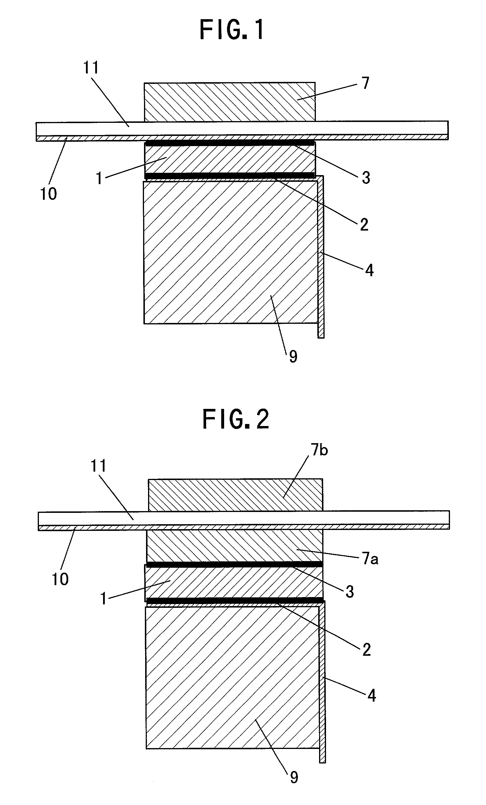
[0077] FIG. 1 is a schematic cross sectional view of an ultrasonic probe of a first embodiment according to the present invention.

[0078] The first embodiment of the present invention is an ultrasonic probe in which a high molecular material layer is provided between a piezoelectric element and an acoustic matching layer, and a conductive layer is disposed on one surface of the high molecular material layer facing to the piezoelectric element so as to be extended out as a GND (ground terminal) of a signal line. This first embodiment provides a high quality ultrasonic probe which allows an electrical terminal to be easily extended out of an electrode of the piezoelectric element. The first embodiment also allows good sensitivity and frequency characteristics in transmitting and receiving the ultrasonic wave to be secured because the high molecular material also serves as a part of the acoustic matching layer. The first embodiment prevents a possible fault caused by a breaking of wire ...

second embodiment

[0086] FIG. 2 is a schematic cross sectional view of an ultrasonic probe of a second embodiment according to the present invention.

[0087] The second embodiment of the present invention is an ultrasonic probe in which a high molecular material layer having a conductive layer formed thereon is a first acoustic matching layer provided on one electrode surface of a piezoelectric element and a second acoustic matching layer so as for the conductive layer to be electrically connected to the first acoustic matching layer, wherein the acoustic impedance of the high molecular material layer is substantially equal to that of the second acoustic matching layer. This second embodiment provides a high quality ultrasonic probe which allows an electrical terminal to be easily extended out of an electrode of the piezoelectric element, and also allows good sensitivity and frequency characteristics in transmitting and receiving the ultrasonic wave to be secured because the high molecular material als...

third embodiment

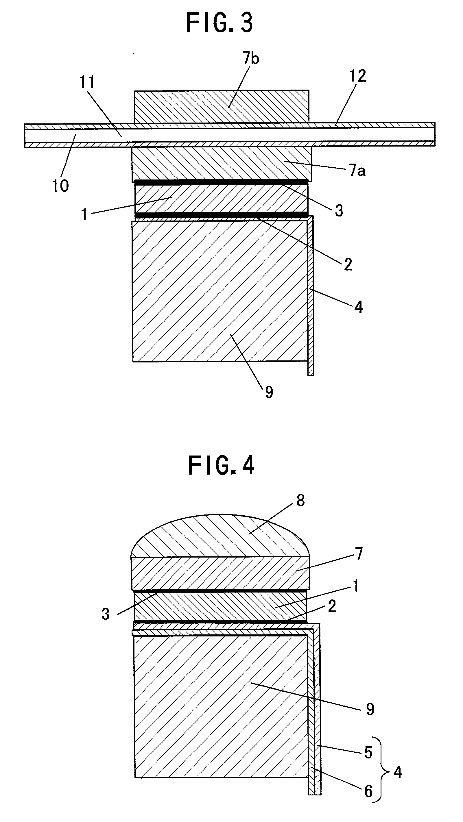
[0096] FIG. 3 is a schematic cross sectional view of an ultrasonic probe of a third embodiment according to the present invention.

[0097] The third embodiment of the present invention provides a ultrasonic probe which allows an electrical terminal to be easily extended out of an electrode of the piezoelectric element, and also allows good sensitivity and frequency characteristics in transmitting and receiving the ultrasonic wave to be secured because the high molecular material also serves as a part of the acoustic matching layer. The third embodiment further makes it possible to reduce a noise since a shield effect is enhanced by a conductive layer formed on a face of a high molecular material layer located on an acoustic matching layer side.

[0098] Referring to FIG. 3, reference numerals 1 to 11 are similar to those of the first and second embodiments shown in FIGS. 1 and 2. That is, the ultrasonic probe of the third embodiment of the present invention has a piezoelectric element 1,...


PUM


Abstract

The object of the present invention is to provide an ultrasonic probe of high performance and high quality. Disclosed is an ultrasonic probe comprising a high molecular material 11 having a conductive layer 10 and is disposed between a piezoelectric element 1 and an acoustic matching layer 7, wherein the high molecular material has an acoustic impedance substantially equal to that of the acoustic matching layer 7. The ultrasonic probe configured as above can be formed into a slim shape which is easy to operate without degrading the performance thereof such as sensitivity, frequency characteristic or the like. The ultrasonic probe is structured so as not to cause electrical problem due to breaking of wire even if the piezoelectric element is cracked by a mechanical impact or the like, and thus a high quality ultrasonic probe can be provided, and the noise can be reduced.

Description

[0001] The present invention relates to an ultrasonic probe to be used in an ultrasonic diagnostic apparatus or the like.DESCRIPTION OF THE PRIOR ART[0002] An ultrasonic probe is used, for example, in an ultrasonic diagnostic apparatus for a human body. One of the conventional ultrasonic probes is disclosed in Japanese Patent Laid-Open Publication No. Hei 8-122310. FIG. 17 shows a structure of the conventional ultrasonic probe. In FIG. 17, a piezoelectric element 31 is an element for transmitting and receiving ultrasonic wave, and each face thereof is provided with electrodes. An acoustic matching layer 37 is made of conductive material and is provided on a face of the piezoelectric element 31 to efficiently transmit and receive the ultrasonic wave for a subject to be examined (human body). The ultrasonic probe further comprises a conductive layer 40 provided on a high molecular film 41 by deposition or other proper means so as to be brought into contact with the acoustic matching l...

Claims


Application Information

Patent Timeline
IPC IPC(8): B06B1/06G10K11/02
CPCB06B1/067G10K11/02
Inventor SAITO, KOETSUKOISHIHARA, YASUSHITAKEDA, JUNICHIFUKASE, HIROKAZU
Owner KONICA MINOLTA INC
Why Eureka
Try Eureka