
Fuel injection method of internal combustion engine and fuel injection apparatus of internal combustion engine

a fuel injection method and internal combustion engine technology, applied in the direction of liquid fuel feeders, machines/engines, instruments, etc., can solve the problems of delayed injection time of injection fuel, fuel injectors, and the inability to inject all the fuel in the combustion chamber

Inactive Publication Date: 2001-09-20
HITACHI LTD +1
View PDF0 Cites 30 Cited by
  • Summary
  • Abstract
  • Description
  • Claims
  • Application Information

AI Technical Summary

Benefits of technology

[0014] Another object of the present invention is to provide a fuel injection method of an internal combustion engine and a fuel injection apparatus of an internal combustion engine, in a fuel injection apparatus (a fuel injector) which is performed by MPI (a multi-point injection) system, an atomization degree of a fuel spray injected from a fuel injector can be more heightened and the fuel spray into an combustion chamber can be supplied suitably.
[0018] The fuel injection apparatus of the internal combustion engine constituted in above according to the present invention, since the fuel injection system in which during the intake stroke a multi-point injection (MPI) system is synchronized is employed and an optimum fuel injection period is established, the mixture of the fuel spray injected from the fuel injection with the intake air flow having the strong fluidization is promoted effectively and the fuel spray is transported to the respective cylinders, accordingly the improvement about the quality of the air-fuel mixture can be obtained. The atomization of the fuel spray can be attained using the fuel upstream swirl type fuel injector. Further, almost spray is formed to direct to the intake air flow having the strong fluidization. Further, since the distance between from the fuel injection hole of the fuel injector to the intake valve of the respective cylinder is shortened, the lowing the penetration force which has been the problem according to the atomization of the fuel spray in the prior art can be compensated. Further, with this construction stated in above, since the alternation in such as the base engine can lessened, the reduction in cost can be improved.
[0019] Further, in the concrete embodiment of the fuel injection apparatus of the internal combustion engine according to the present invention, the-injection hole axis of the fuel injector is arranged to direct in the dish port of the intake valve, and further the fuel spray injected from the fuel injector is generated to orient the inner wall face which is the side opposed to the inner wall face of the intake valve in the fuel injector side. Accordingly, as to the fuel spray configuration, in the inner wall face side of the cylinder head in the fuel injector side the spread angle is small (the fuel spray amount is small) and in the inner wall face side of the opposed side the spread angle is large (the fuel spray amount is large), as a result the adhesion amount of the fuel spray to the inner wall face of the cylinder head can be reduced.
[0020] Further, in the another concrete embodiment of the fuel injection apparatus of the internal combustion engine according to the present invention, the injection hole axis of the fuel injector is arranged to direct in the dish port of the intake valve, and further the fuel spray injected from the fuel injector is deflected to the inner wall face -side of the side opposed with the inner wall face of the cylinder head in the fuel injector side. And also in the cross-section which is orthogonal to the injection hole axis of the fuel injector the fuel spray is generated to have the flatness shape (for example, with the two intake valves the fuel spray is substantially concentrated) and when the intake valve is opened, the intake air flow having the strong fluidization which is flown from the intake air flow control apparatus can be transported.
[0022] As a result, since the alternation of the layout for installing the base engine does not generated, the reduction in the cost can be attained. Further, by suiting the flatness degree and the deflection degree in the desirable form of the fuel spray can be selectively in compliance with request, it is possible to obtain the correspondence of the various kinds and comparative styles in the fuel spray.
[0023] Further, according to the compatibility of the atomization of the fuel spray, the air-fuel mixture having the good quality can be generated, the improvement of the exhaust gas purification and the improvement of the fuel consumption can be attained.

Problems solved by technology

In the above stated direct injection engine, there is a problem from a manufacturing cost in accordance with many alternations about an engine base, and it has need to provide a piston head which has a specific shape configuration and to require some surrounding devices.
However, since the kinetic energy of the above stated atomized injection fuel is smaller than the kinetic energy of the injection fuel having the ordinary particle diameters, there is a problem of a delay in time of the injection fuel in which a penetrating force of the fuel injection is made small and a time of the injection fuel for reaching to the cylinder from the fuel injection apparatus (the fuel injector) is delayed.
When the delay in time of the injection fuel if the fuel injector invites, there is a problem in which all of the injection fuel can not be entered in a combustion chamber of the engine during an intake stroke time.
In other words, the delay in time of the injection fuel of the fuel injector to the combustion chamber of the engine appears to a transportation delay of the injection fuel to the combustion chamber of the engine.
However, in the prior arts, as stated in above only the fuel wet characteristic can be dissolved, there is no particular consideration about the dissolution of the delay in time of the injection fuel during the intake stroke time or the transportation delay of the injection fuel during the intake stroke time.

Method used


Image

  • Fuel injection method of internal combustion engine and fuel injection apparatus of internal combustion engine
  • Fuel injection method of internal combustion engine and fuel injection apparatus of internal combustion engine
  • Fuel injection method of internal combustion engine and fuel injection apparatus of internal combustion engine

Examples


Embodiment Construction

[0047] Hereinafter, a fuel injection method of an internal combustion engine and a fuel injection apparatus of an internal combustion engine of one embodiment according to the present invention will be explained referring to the drawings.

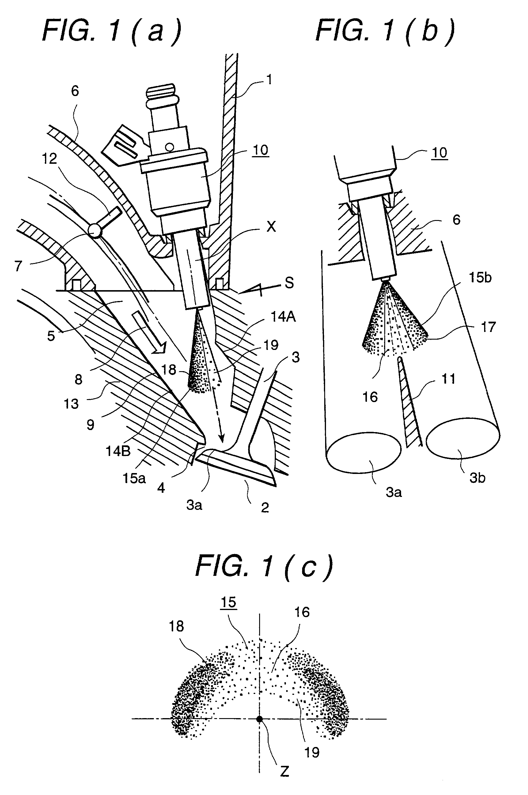
[0048] FIG. 1(a) and FIG. 1(b) are views showing a mounting state for mounting to a multi-cylinder internal combustion engine of a fuel injection apparatus (a fuel injector) of one embodiment according to the present invention. FIG. 1(a) is a partially cross-sectional view of the mounting state of the fuel injector, and FIG. 1(b) is a view which is seen from a S direction of FIG. 1(a) and showing a positional relationship between an intake valve and the fuel injector.

[0049] A reference numeral 1 is one of cylinders of the multi-cylinder internal combustion engine and a reference numeral 2 is a combustion chamber, a reference numeral 3 is an intake valve for opening and closing an intake port 4, a reference numeral 5 is an intake air passage having a...


PUM


Abstract

In a fuel injection apparatus of an internal combustion engine comprising a fuel injector, an intake valve device for opening and closing an intake port, and an intake air flow control device arranged in an upstream side of the intake valve device, a fuel injection is synchronized with an intake stroke of the engine. A fuel spray is oriented to an inner wall face which is positioned in an opposite side to an inner wall face of a cylinder heads in a fuel injector side and the fuel spray is transported by an air flow having a strong fluidization which is entered from the intake air control device. In a port injection lean burn engine, an adhesion to the wall face according to the fuel spray can be reduced, and a quality and a formation state of an air-fuel mixture in a cylinder can be improved.

Description

[0001] 1. Technical Field[0002] The present invention relates to a fuel injection method of an internal combustion engine and in particularly to a fuel injection method of an internal combustion engine in which an atomization of a fuel spray injected from a fuel injector is heightened and the fuel spray is supplied to an intake manifold, and a fuel injection apparatus of an internal combustion engine and in particularly to a fuel injection apparatus of an internal combustion engine in which an atomization of a fuel spray injected from a fuel injector is heightened and the fuel spray is supplied to an intake manifold.[0003] 2. Prior Art[0004] Recently, from an aspect of an environment protection, an exhaust gas regulation and a fuel consumption regulation in an automobile field has enforced exclusively from year to year. Coming under the influence of these requirements, to improve an exhaust gas purification and the fuel consumption of an internal combustion engine, various kinds of ...

Claims


Application Information

Patent Timeline
IPC IPC(8): F02M51/06F02M61/12F02M61/16F02M61/18F02M65/00F02M69/04
CPCF02M51/0675F02M51/0682F02M61/12F02M61/162F02M61/184F02M61/1853F02M65/00F02M69/044
Inventor OKAMOTO, YOSHIOKADOMUKAI, YUZOMIYAJIMA, AYUMUNAGANO, MASAMISOMENO, TADASHI
Owner HITACHI LTD
Learn More