
Semi-elliptical sail system for wind-propelled vehicles

Inactive Publication Date: 2001-11-08
FINK LOWELL S
View PDF0 Cites 11 Cited by
  • Summary
  • Abstract
  • Description
  • Claims
  • Application Information

AI Technical Summary

Benefits of technology

0121] The several advantages of the present invention are considered, first, as they favor vertically deployed headsails, then as they favor horizontally deployed headsails. In each case, a distinction is made between in-place non-overlapping sails or jibs, and in-place overlapping sails, or genoas.
0122] a. Controlled sail deployment and recovery;
0123] b. Inte

Problems solved by technology

Such bags were an important advance in protecting mainsails, but no satisfactory equivalent appeared for the protection of headsails, where no boom or mast was available for attaching such a bag.
Without regard to the shortcomings of such bags, they have common characteristics particularly inappropriate to use for protecting headsails.
It also goes far beyond the abovementioned rudimentary jib bags which simply allowed fitting a jib into a bag while the jib remained attached to its stay, but did not provide automatic flaking.
More importantly, such bags required on deck sail handling in dangerous conditions and did nothing whatever to control the sail during deployment and recovery.
As such, known stowage bags, whose use is limited to mainsail stowage, and whose open forward end is in the wind shadow of the mast, are unsuitable for headsail stowage.
b. Airflow leaking above and below the extremities of a sail diminishes performance.
However, in high winds, furling becomes difficult, and furling sails are not controlled during recovery.
Sailors who consider a vertically deployed sail more efficient and safer than a furling sail. have no choice but to continue using conventional sail bags, which must be removed, stowed, and replaced, before and after use, involving considerable time and effort.
They likewise continue to struggle with lowering an uncontrolled working jib and to secure it once they get it on the deck.

Method used


Image

  • Semi-elliptical sail system for wind-propelled vehicles
  • Semi-elliptical sail system for wind-propelled vehicles
  • Semi-elliptical sail system for wind-propelled vehicles

Examples


main embodiment

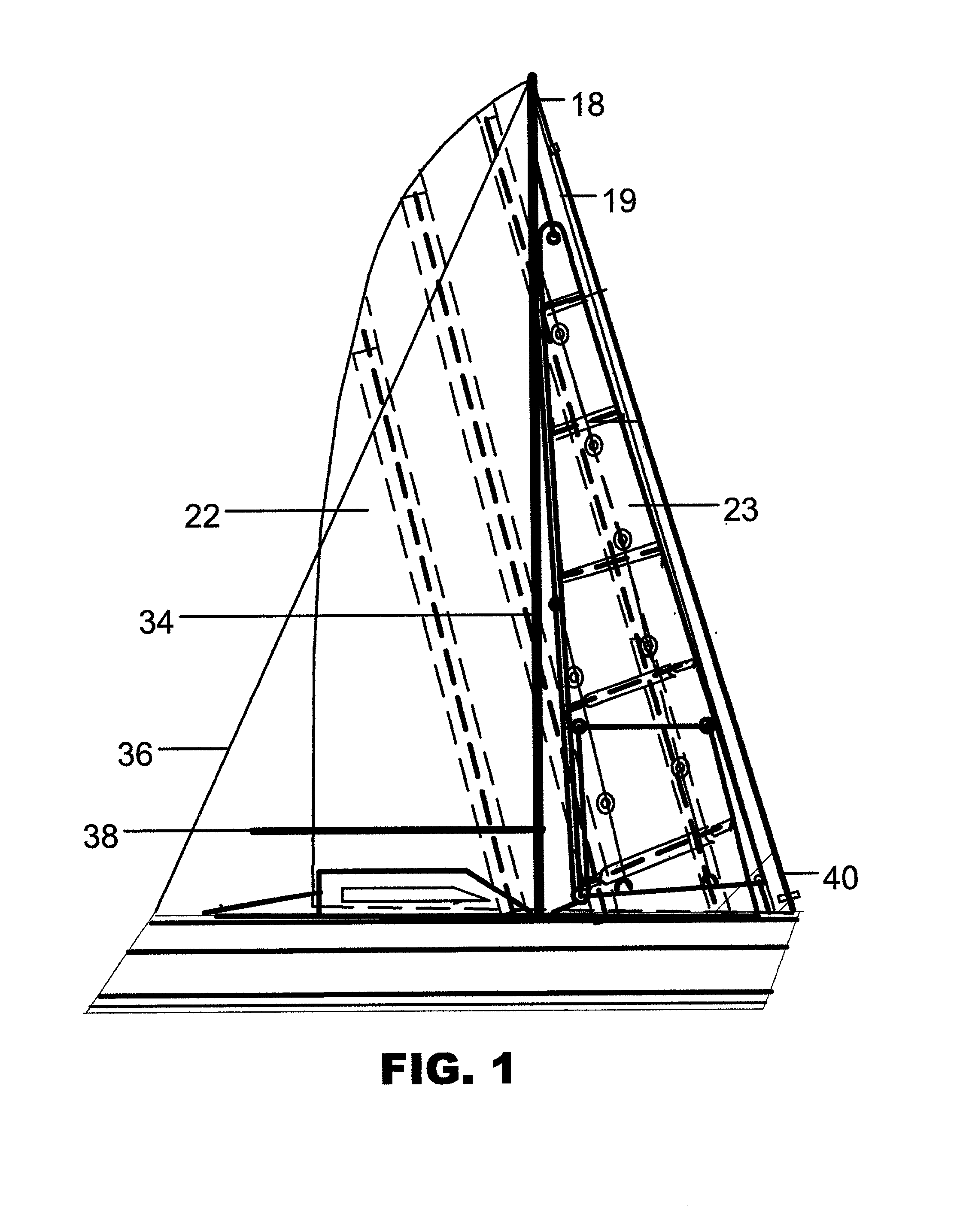
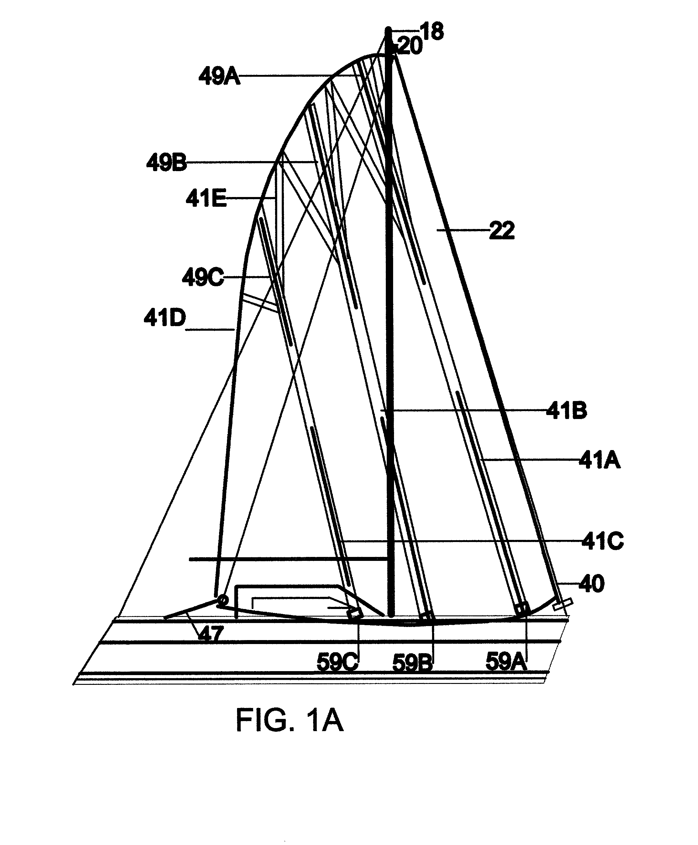
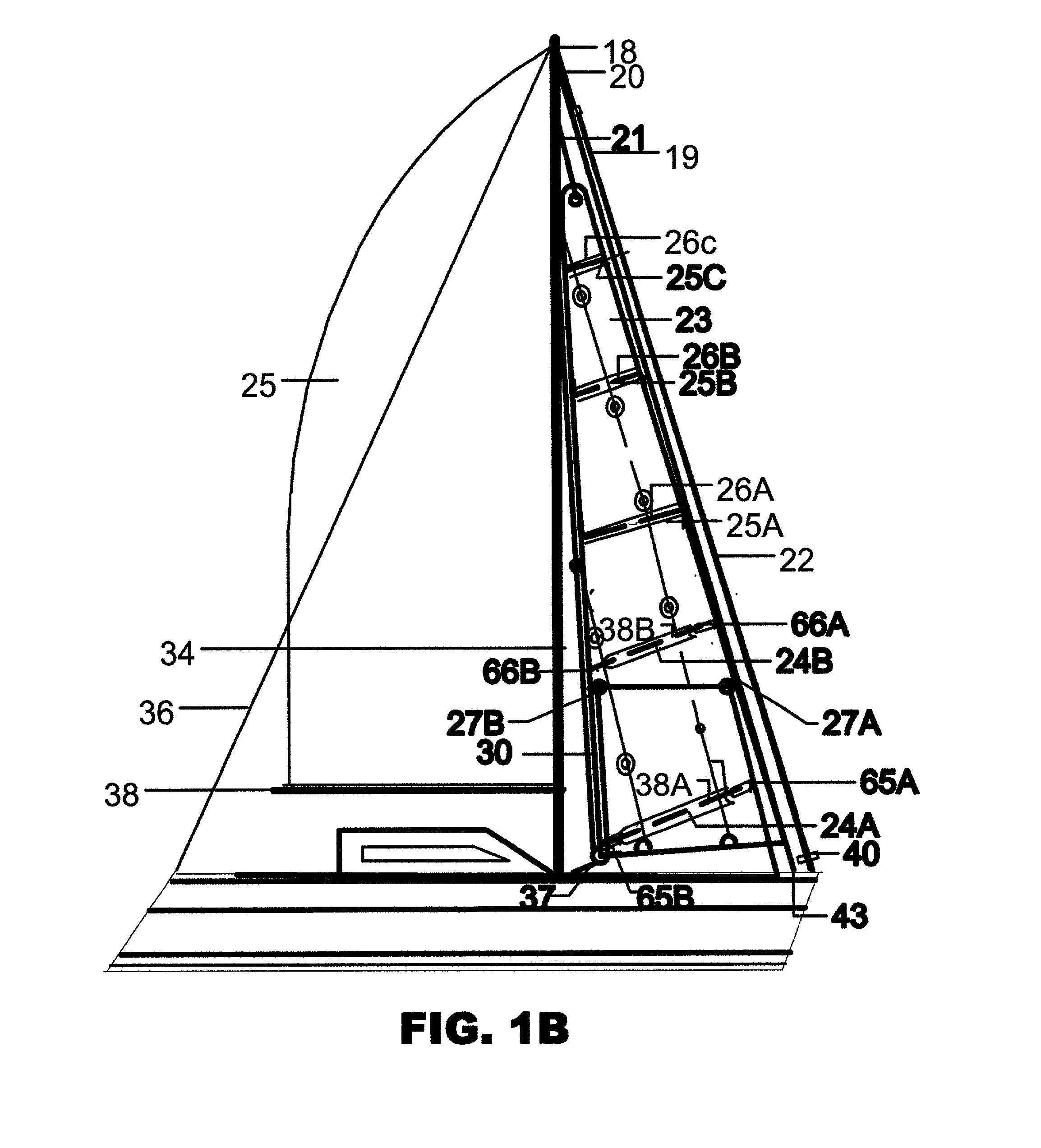
[0410] The main embodiment of the present invention comprises a sail system having three basic components:

[0411] 1. a semi-elliptical roller-furling convertible genoa-jib 22

[0412] 2. a semi elliptical self-tacking Rib 23; and

[0413] 3. an automatic jib stowage bag 44

[0414] The said sail system reconciles several potentially conflicting design objectives, namely:

[0415] 1. performance

[0416] 2. crew safety

[0417] 3. ease of use

[0418] 4. durability

[0419] 5. cost effectiveness

[0420] 6. broad market appeal

[0421] Each component of the present invention represents a solution to a problem that has heretofore been considered insurmountable. Each such problem and its solution are discussed below.

Headsail Performance--Background

[0422] From the earliest times it was believed that more headsail area necessarily yielded higher sailing speed and better windward performance. Later it was argued that while more sail area improves performance when sailing with the wind aft of the beam, windward performa...


PUM


Abstract

A versatile multi-component sail system for propelling any wind-propelled vessel at optimum efficiency on all points of sail with a minimum number of sails, with minimum crew effort, and with all sail handling done from the safety of the cockpit, comprising one or a plurality of horizontally deployed in-place semi-elliptical convertible genoa-jibs (22); vertically deployed, semi-elliptical self-tacking jibs (23); and low-profile in-place automatic jib stowage bags (44). The system's integral sails and sail stowage and control means remain in place and are active throughout the sail deployment, navigation and sail recovery cycle. One or all system components may be used as needed to provide a synergistic combination of performance, safety, and convenience to any wind-propelled vessel over the widest possible range of conditions.

Description

CROSS REFERENCE TO RELATED APPLICATIONS[0001] This application is entitled to the benefit of Provisional Patent Application Ser. No. 60 / 182,207 Filing date Feb. 14, 2000.BACKGROUND[0002] 1. Field of Invention[0003] This invention relates to a sail system for wind-propelled vehicles, specifically a system comprising semi-elliptical sails and the means for the deployment, control, recovery and stowage of such sails.[0004] 2. Description of Prior Art[0005] Safety and speed are at opposite poles in all too many disciplines, among them sailing in its various forms. In recent years some progress has been made in reconciling the two objectives, but the major obstacle to safe, high performance sailing with low crew effort is the seeming incompatibility between the ideal, semi-elliptical sail form and safe, easy sail handling.[0006] Historically most boats required many sails merely to approximate the ideal sail configuration, even with resort to continual and often dangerous on-deck sail ch...

Claims


Application Information

Patent Timeline
IPC IPC(8): B63H9/06B63H9/10
CPCB63H9/06B63H9/0642B63H9/1021B63H9/1028B63H9/1092
Inventor FINK, LOWELL S.
Owner FINK LOWELL S
Learn More