Radio receiver and signal amplifying method in radio receiver

a radio receiver and receiver technology, applied in substation equipment, electrical equipment, climate sustainability, etc., can solve the problems of reducing the s/n ratio of cdma signal, reducing the power consumption, and very low utilizing factor of the band, so as to achieve the effect of reducing power consumption

Inactive Publication Date: 2001-11-15
FUJITSU LTD
View PDF5 Cites 30 Cited by
  • Summary
  • Abstract
  • Description
  • Claims
  • Application Information

AI Technical Summary

Benefits of technology

[0018] In view of the foregoing problems, the present invention has been conceived, and its object is to provide a radio receiver and a method of amplifying the signal for use in the same which may amplify the received signal according to plural types of radio communication systems so as to allow the signal of each radio communication systems to be each amplified optimally to thereby achieve reduction of the power consumption.

Problems solved by technology

This CDMA system (hereinafter referred to simply as "CDMA") has a disadvantage that, because the frequency band covered by the base station is simultaneously occupied by a plurality of mobile terminals, the utilizing factor of the band is very low.
Why, during the CDMA mode operation, the high IIP3 is required is that, as described above with reference to FIG. 8(b), in the CDMA system, the power density of the spectrum of the transmitted signal is extremely low as compared with that of the FM system and that if the tertiary distortion caused by the tertiary harmonic wave signal of the FM system carrier signal (interference signal) takes place greatly to the frequency area of this spectrum for interference, then the S / N ratio of the CDMA signal can be greatly degraded resulting its abnormal reception.
However, during the FM mode operation, since it does not call for such a high IIP3, if the IF amplifier 105 is used in common with the CDMA and FM modes, then, as compared with the existing receiving front end dedicated to the FM mode, the current amount consumption can become too much resulting in a great increase of power consumption.

Method used


Image

  • Radio receiver and signal amplifying method in radio receiver
  • Radio receiver and signal amplifying method in radio receiver
  • Radio receiver and signal amplifying method in radio receiver

Examples


first embodiment

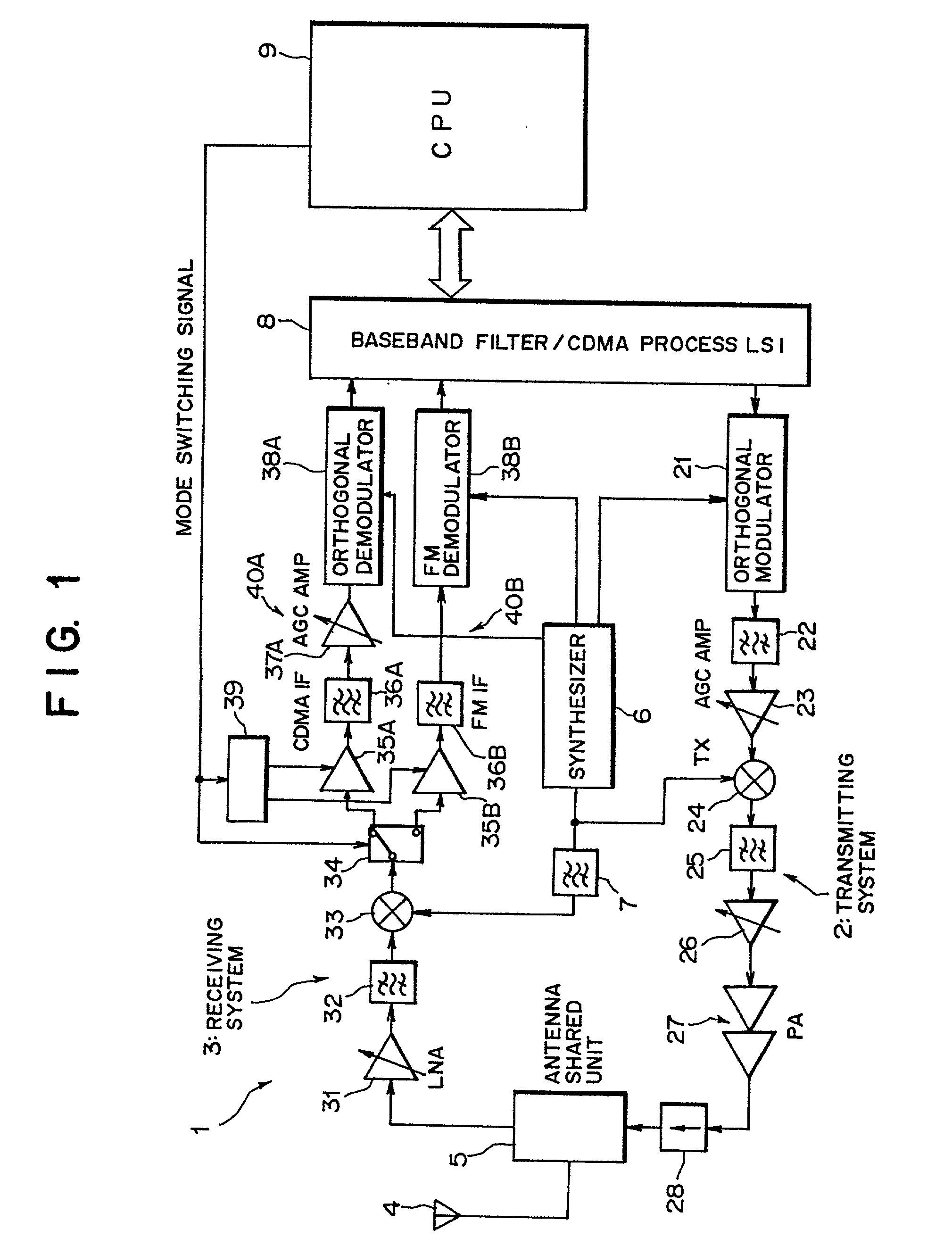
[0054] FIG. 1 is a block diagram illustrating a construction of a portable radio mobile terminal (radio receiver) according to the invention, in which a portable radio mobile terminal 1 is constructed as a dual mode terminal which may be used in either of the service areas for a CDMA system [first communication system (digital radio communication system utilizing the spread spectrum system)] and an FDMA system [second communication system (analog radio communication system)] . The portable radio mobile terminal 1, as shown in FIG. 1, is provided with a transmitting system 2 and a receiving system 3, and a single antenna 4 is shared in common between the transmitting system 2 and the receiving system 3 by means of an antenna shared unit 5. Incidentally, in this FIG. 1, reference numeral 6 denotes a synthesizer, 7 a bandpass filter (BPF), 8 a large-scale integrated circuit (LSI) and 9 a central processing unit (CPU), whose functions will be described later.

[0055] As shown in FIG. 1, t...

second embodiment

[0101] (B) Description of the Second Embodiment

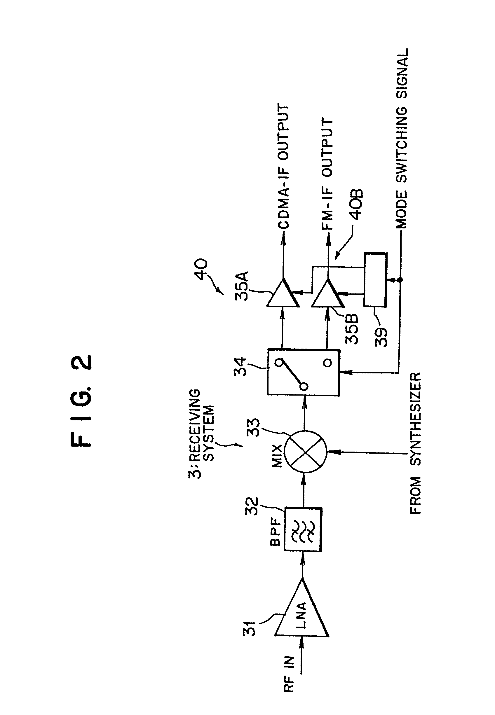
[0102] FIG. 5 is a block diagram illustrating a construction of the portable radio mobile terminal (radio receiver) according to a second embodiment of the invention, in which a portable radio mobile terminal 1' differs from the terminal 1 of FIG. 1 in that an IF amplifier 35 common to the CDMA and FM (TACS) systems is provided at the rear stage of a mixer 33 while a switch 34 is provided at the rear stage of the IF amplifier 35 and that, in place of the power switching circuit 39, a bias adjusting circuit 39' is provided.

[0103] That is, in the portable radio mobile terminal 1' according to the second embodiment of the invention (hereinafter, sometimes referred to simply as "terminal 1'" or "dual mode terminal 1'"), the switch 34 is provided at the rear stage of the IF amplifier 35 so as to divide the rear stage of the IF amplifier 35 into two demodulating systems 40A and 40B. Incidentally, other components (assigned with the same signs...


PUM


Abstract

The present invention relates to a radio receiver and a method of amplifying a signal in the same. The apparatus comprises a receiving system capable of receiving a radio signal according to plural types of radio communication systems while this receiving system is provided with amplifiers adapted for amplifying plural types of received signals to amplify received signals according to the plural types of radio communication systems to carry out an optimal amplifying process relative to the signal for each radio communication system. As a result, the power consumption may be reduced.

Description

[0001] (1) Field of the Invention[0002] The present invention relates to a radio receiver and a signal amplifying method in radio receiver and, in particular, to a radio receiver which is capable of receiving the electric waves (radio signals) according to plural types of radio communication modes (systems) and a method of amplifying signals for use in the same.[0003] (2) Description of the Related Art[0004] In the field of the radio communication technique, in particular, the mobile communication technique as in the personal handy phone system, a radio communication system called Frequency Division Multiple Access (FDMA) system has been well known in which the frequency band dealt with by a single base station is divided to be allocated to a plurality of mobile equipment (mobile terminals) so that they may simultaneously make access to the single base station for communication. Incidentally, in this FDMA system, in general, the FM communication adapted system(analog communication s...

Claims


Application Information

Patent Timeline
Patent Type & Authority Applications(United States)
IPC IPC(8): H04B1/16H04B1/26H04B1/3822H04B1/40
CPCH04B1/406Y02B60/50
Inventor WATANABE, HIDEKI
Owner FUJITSU LTD
Why Eureka
Try Eureka