Low disturbance pulsatile flow system

a flow system and low disturbance technology, applied in the field of coronary implants, can solve the problems of high flow-dependent nature of thrombosis, major biocompatibility, acute or long-term device failure, etc., and achieve the effect of minimizing background noise, minimizing length and discontinuities, and reducing the effect of thrombotic signal

Inactive Publication Date: 2001-12-20
MASSACHUSETTS INST OF TECH
View PDF0 Cites 12 Cited by
  • Summary
  • Abstract
  • Description
  • Claims
  • Application Information

AI Technical Summary

Benefits of technology

0012] A model has been created to observe the physiological, controllable flows in a manner to create a large thrombotic signal, while minimizing the effects of background noise. This is accomplished by minimizing the length and discontinuities of a tubing loop into which a prosthetic, such as a stent or a graft,

Problems solved by technology

Biocompatibility has been a major issue in the ability to use prosthetic implants in clinical settings.
These reactions, ranging from thrombosis, to inflammation, to restenosis, can result in acute or long-term device failure.
The thrombotic reaction is one of the earliest responses to implantation and by virtue of its potential for rapid acceleration and complete luminal occlusion, one of the most devastating.
One difficulty that has limited the extensive examination of bioprosthetic thrombosis is the highly flow-dependent nature of thrombosis and lack of widely applicable flow models.
It is not ideal as a large air/blood interface can cause protein aggregation and denaturation, creating a significant departure from the physiological situation.
Furthermore, this method does not allow for arterial flow profiles to be obtained.
However this is not helpful when studying actual coronary prosthetic configurations as the chambers and flow rates are not arterial in nature.
However, there are several factors that reduce the potential of this system to study stent thrombosis.
One is the level of background noise that is created with the large surface area of peristaltic tubing and the roller pump's action.
Furthermore, placing the stent in a discontinuous 4 mm region not only increases system background noise, but substantially pert

Method used


Image

  • Low disturbance pulsatile flow system
  • Low disturbance pulsatile flow system
  • Low disturbance pulsatile flow system

Examples


Embodiment Construction

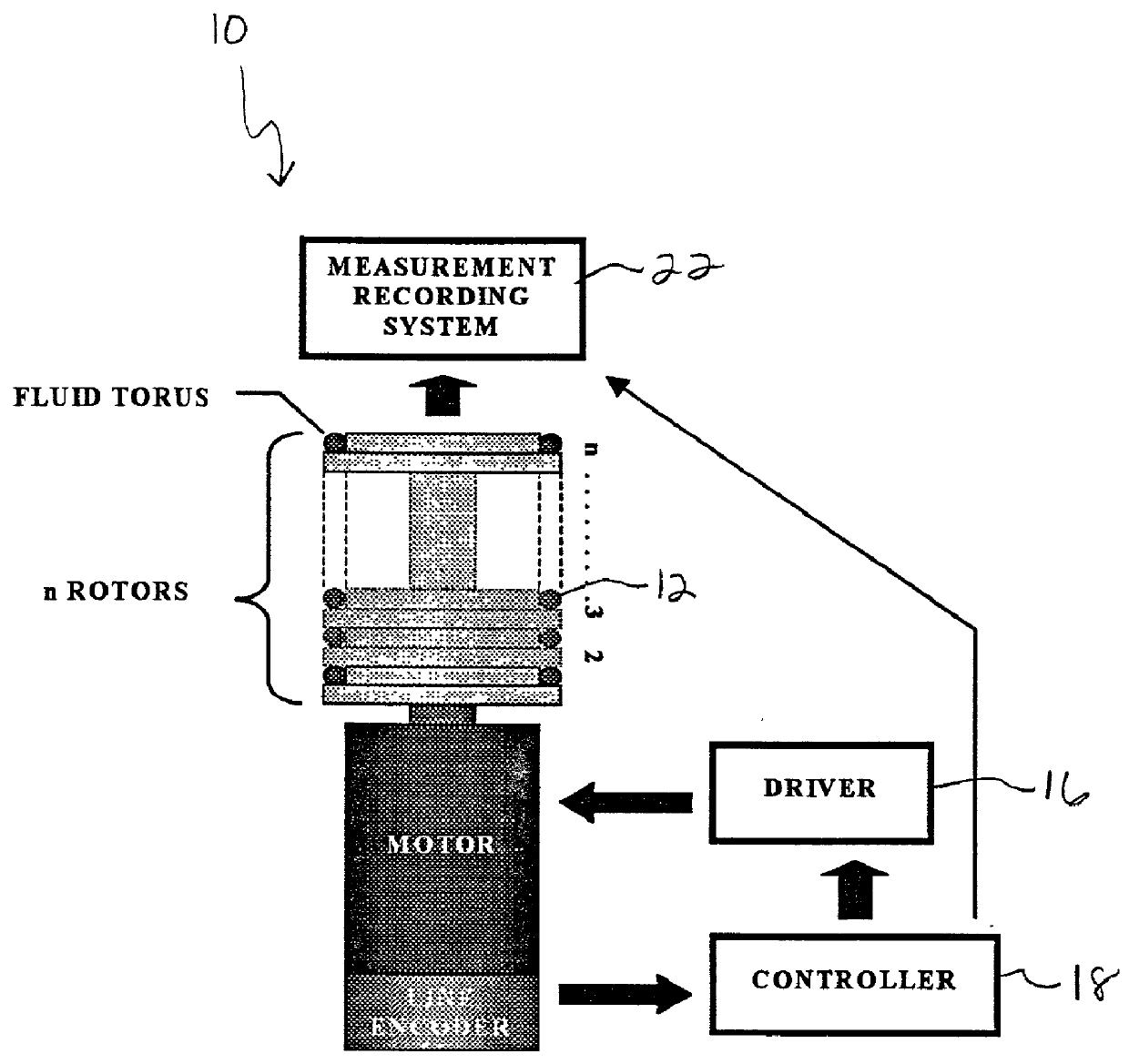
[0034] As shown initially in FIG. 1, is a low-disturbance, pulsatile, in vitro flow device is generally

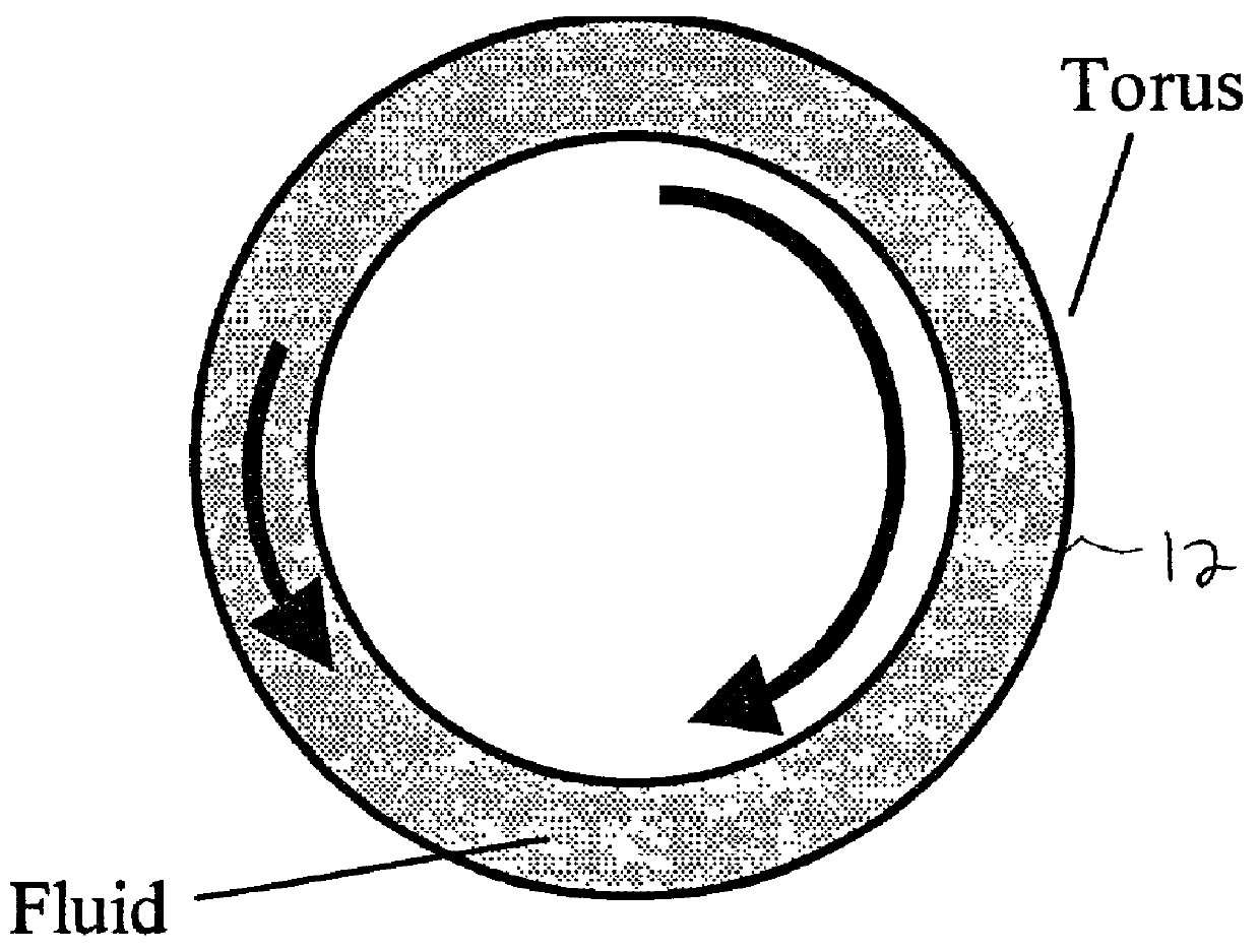
[0035] shown at 10. The device includes a fluid torus 12, rotor-stage 14, driving motor 16, motion controller 16, and a measurement system 20 utilized to observe the physiological, controllable flows in a manner to create a large thrombotic signal. The system is usually utilized in an incubator, not shown, to keep the samples at a stable temperature. As described in detail below, this includes placing a stent 24 or a graft in a torus or loop 12, as seen in the Figures. The loop 12 is then filled with the desired blood constituents and spun about its axis in a prescribed fashion. This spinning is controlled in such a way as to modulate the inertial flow of the contained fluid through transmitted shear forces from the tubing wall, thereby creating a low disturbance flow.

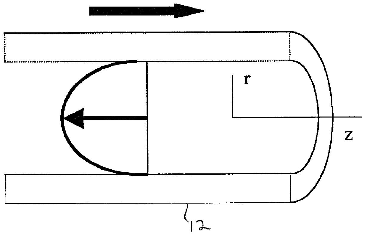
[0036] To create the desired flow profiles, the fluid-filled torus 12 is rotated about its axis. When impulsively s...


PUM


Abstract

A flow system device used for testing/creating fluid flow. The system comprises at least one fluid filled loop and a rotor stage for maintaining at least one rotor. The loop is positioned on the rotor. The device also includes a driving motor for rotating the rotor stage and a motion controller for controlling the speed and directional motion of the motor.

Description

BACKGROUND OF THE INVENTION[0001] The invention relates to the field of coronary implants, and in particular to a low disturbance, pulsatile, in vitro flow circuit for modeling coronary implant thrombosis.[0002] Biocompatibility has been a major issue in the ability to use prosthetic implants in clinical settings. One such set of applications includes vascular prosthesis such as endoluminal stents or grafts to allow blood to flow either through or past a previously stenosed vascular segment. When such a foreign structure comes into contact with tissue and blood, a variety of biological consequences ensue. These reactions, ranging from thrombosis, to inflammation, to restenosis, can result in acute or long-term device failure. Not only is coagulation responsible for the obvious occurrences of acute thrombotic events, but sub-clinical levels have also been implicated as a player in the pathophysiology of restenosis through the release of chemical mediators and by providing a scaffold ...

Claims


Application Information

Patent Timeline
IPC IPC(8): A61F2/06
CPCA61F2/06
Inventor EDELMAN, ELAZERKOLANDAIVELU, KUMARAN
Owner MASSACHUSETTS INST OF TECH
Why Eureka
Try Eureka