Feed pump

Inactive Publication Date: 2002-01-31
VITESCO TECH GMBH
View PDF1 Cites 1 Cited by
  • Summary
  • Abstract
  • Description
  • Claims
  • Application Information

AI Technical Summary

Benefits of technology

[0008] This configuration allows the radially outer region of the impeller to be tilted or slightly displaced by an intended amount in the casing. The position may be adjusted in the casing, for example, by the forces of the axial bearing of the impeller. Rubbing of the impeller on the casing is reliably avoided as a result. Furthermore, the formation of noise is kept particularly low due to the present invention. The feed pump according to the present invention has particularly high efficiency due to the constant sealing gap in the region adjacent to the guide blades.
[0009] To generate the pivotability of the impeller with respect to the shaft, a particularly large play may be arranged between the impeller and the shaft. However, the large play produces rattling noises when the shaft is driven and in the case of fluctuations in flow in the feed pump. According to an embodiment of the present invention, rattling noises may be kept particularly low when the impeller has, in its region adjacent to the shaft, a depression which surrounds the shaft. This configuration allows the connection of the impeller to the shaft to be restricted to intended dimensions for an intended height of the impeller. In the case of the very small play of the impeller with respect to the shaft, these dimensions are critical for the intended pivotability of the impeller. Another advantage of this configuration is that the impeller does not rub on the casing in the region of the depression.
[0010] The depression may be arranged on one end face of the impeller. However, the generation of noise in the feed pump according to the present invention is further reduced when a depression is arranged in each of the two end faces of the impeller.
[0011] According to another embodiment of the invention, play between the shaft and the impeller is kept particularly low, along with an intended pivotability of the impeller, when the impeller is designed to be elastic at least in its radially inner region. In the most favorable case, the impeller may be pressed on the shaft. The elastic design of the radially inner region allows simple pivotability and axial movability of the radially outer edge of the impeller.

Problems solved by technology

A problem with the known feed pump is that positional tolerances and the angle of inclination of the shaft with respect to the casing may lead to the impeller rubbing on the casing.
This rubbing generates loud noises and, moreover, reduces the efficiency of the feed pump.
However, the large play produces rattling noises when the shaft is driven and in the case of fluctuations in flow in the feed pump.

Method used


Image

  • Feed pump
  • Feed pump
  • Feed pump

Examples


Embodiment Construction

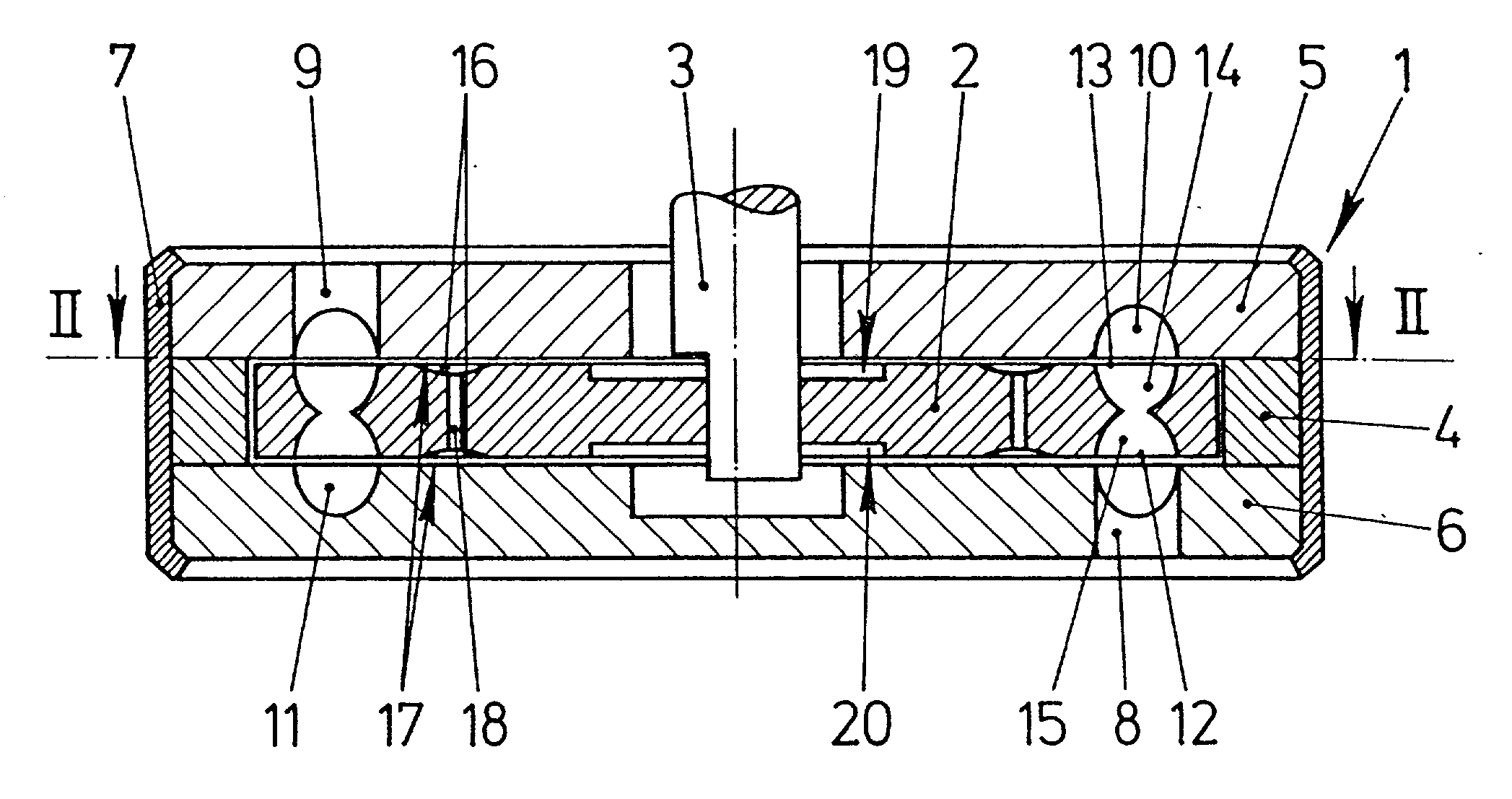
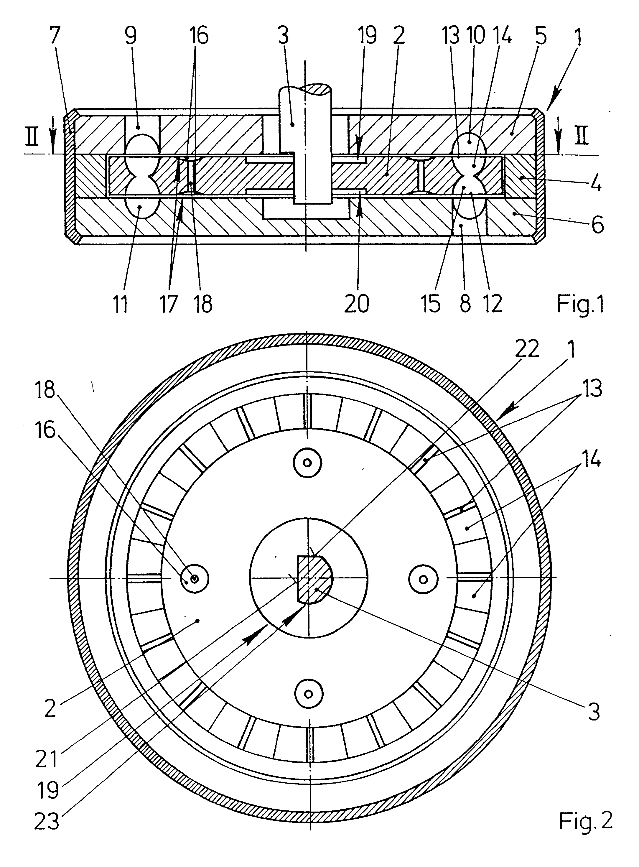
[0023] FIG. 1 is a sectional view of a feed pump according to the present invention designed as a side-channel pump with an impeller 2 rotatably arranged in a casing 1. The impeller 2 is arranged so that it is fixed with respect to rotation relative to a driven shaft 3 and slightly axially displaceable on the driven shaft 3. The shaft 3 may, for example, be designed as a motor shaft of an electric motor (the electric motor is not illustrated in FIG. 1). The casing 1 includes two casing parts 5, 6 held with clearance by a ring 4 and a sheet-metal strip 7 rolled at the edges of the casing parts 5, 6 and intended for prestressing the casing parts 5, 6 against the ring 4. An inlet channel 8 is arranged in one of the casing parts 6 and an outlet channel 9 is arranged in the other casing part 5. The inlet channel 8 and the outlet channel 9 are respectively connected to part-annular channels 10, 11. The impeller 2 has blade chambers 14, 15 arranged in the region of the part-annular channel...


PUM


Abstract

In a feed pump designed as a side-channel pump, an impeller is held so as to be slightly pivotable with respect to a shaft about an axis running transversely to the shaft. The impeller is thereby adaptable to tolerances of a casing. Rubbing of the impeller on the casing is also prevented as a result. The feed pump consequently generates a particularly low level of noise.

Description

[0001] 1. Field of the Invention[0002] The invention relates to a feed pump for feeding fuel out of a fuel tank of a motor vehicle or for feeding washing fluid of a windshield washing system including a casing, an impeller arranged in the casing and connected on a driven shaft such that the impeller is fixed with respect to rotation relative to the driven shaft and a portion of the impeller is arranged with a slight clearance relative to the casing.[0003] 2. Description of the Related Art[0004] Feed pumps for feeding fuel out of a fuel tank are or for feeding washing fluid for a windshield washing system are typically designed as peripheral pumps or side-channel pumps and are known from practice. Each of these known pumps includes a casing which usually has two casing parts with a recess for the impeller. A particularly small sealing gap is arranged between the impeller and the casing parts in radially outer regions of the impeller which are adjacent to guide blades. An axial slidin...

Claims


Application Information

Patent Timeline
IPC IPC(8): F04D29/18F04D5/00
CPCF04D29/188F04D29/18
Inventor MARX, PETERJAGER, BERND
Owner VITESCO TECH GMBH
Why Eureka
Try Eureka