Automatic analysis apparatus

Inactive Publication Date: 2002-02-28
HITACHI LTD
View PDF4 Cites 14 Cited by
  • Summary
  • Abstract
  • Description
  • Claims
  • Application Information

AI Technical Summary

Problems solved by technology

However, in the method of inserting a spatula-shaped agitation rod into the reaction vessel, a phenomenon called carry-over occurs where reagent or sample deposited on the agitation rod affects the result of the following analyses, if a sufficient washing of the agitation rod cannot be ensured.
For this reason, the method of giving vibration to agitation rod results in increased costs.
The method of using reagent including magnetic particulates requires reagent to be developed, and this raises cost problems.
The method of installing a barrier to the reaction vessel to provide agitation through pneumatic pressure requires the reaction vessel to be subjected to special processing, and this also involves cost problems.
However, if excessive ultrasonic wave intensity is used f

Method used


Image

  • Automatic analysis apparatus
  • Automatic analysis apparatus
  • Automatic analysis apparatus

Examples


first embodiment

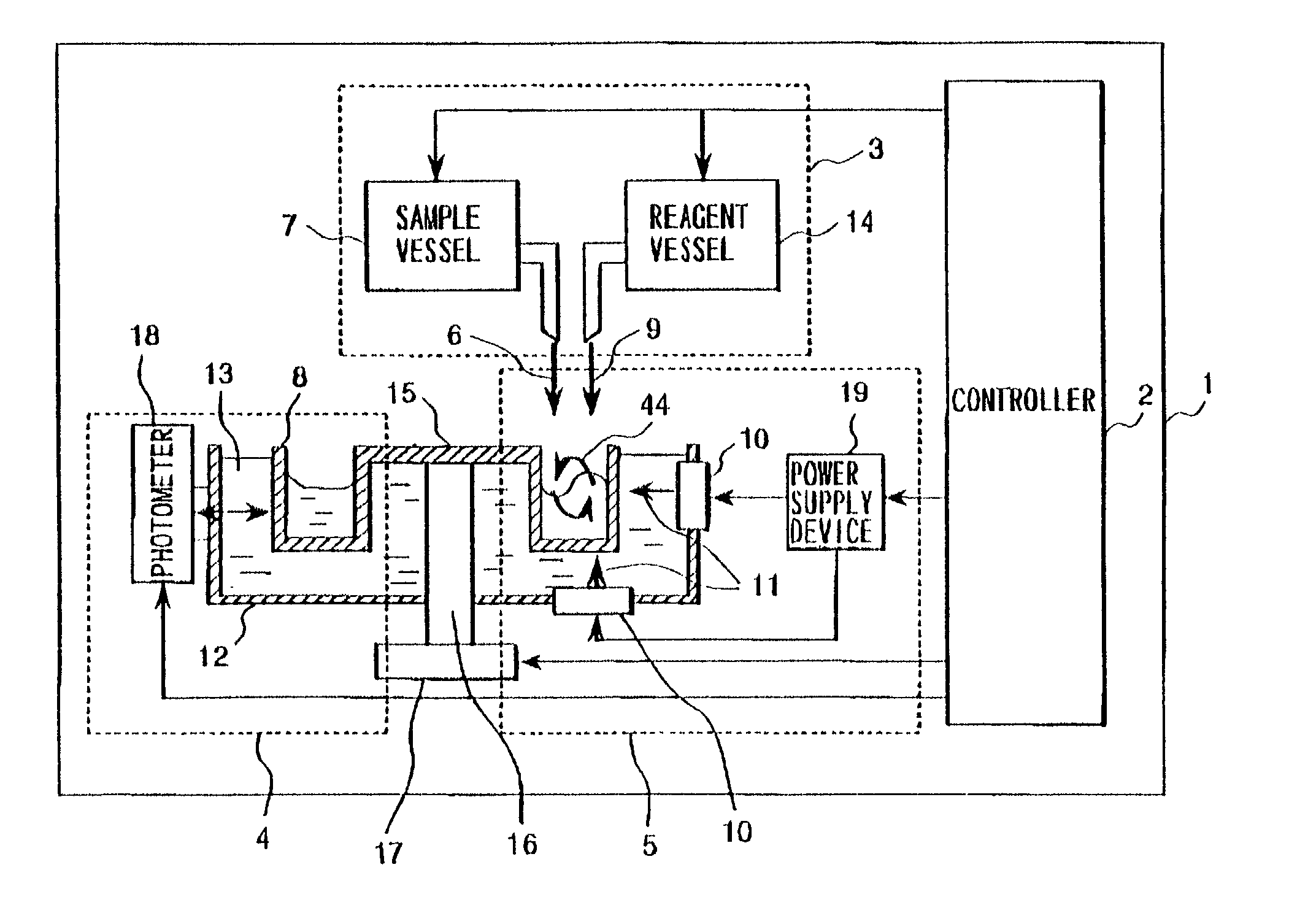
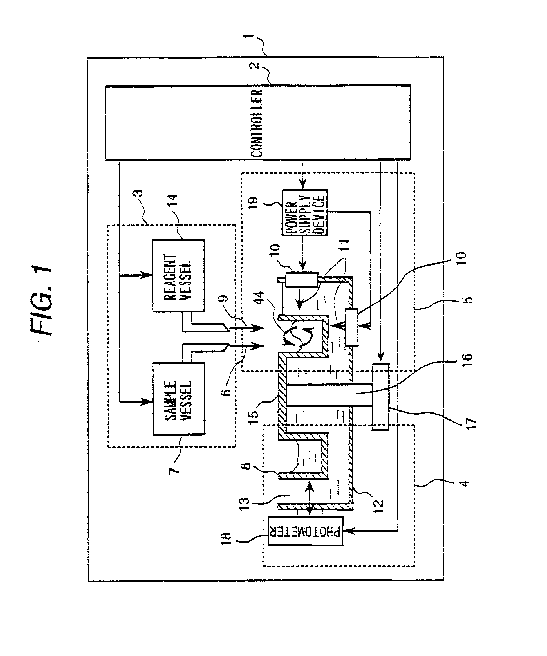
[0043] FIG. 1 is a schematic diagram of an automatic analyzer representing the present invention.

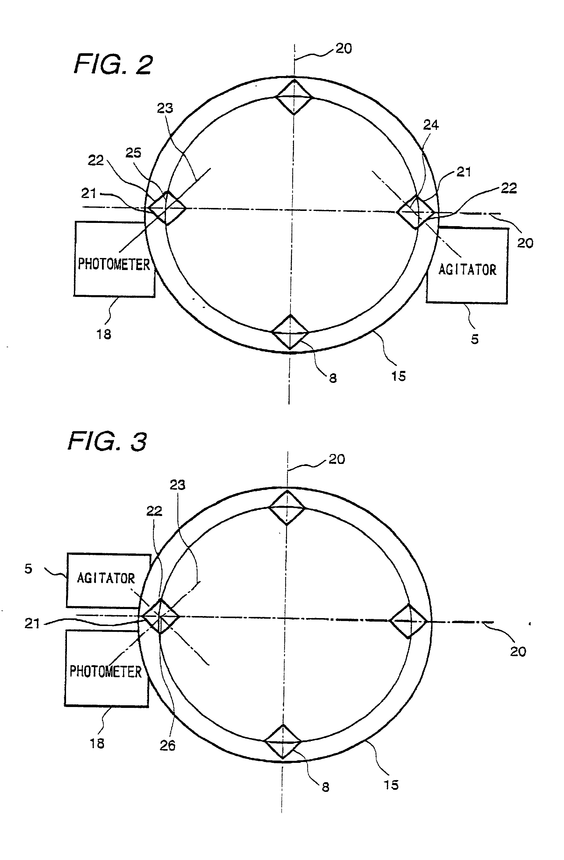
[0044] FIG. 2 is a top view of the reaction disk 15 in the first embodiment of the present invention.

[0045] In FIGS. 1 and 2, the automatic analyzer 1 comprises a controller 2, storage device 3, analyzer 4, and agitator 5.

[0046] The controller 2 consists of an electronic circuit to provide detailed operation control of each section and a storage device, and controls system operations.

[0047] The storage device 3 consists of a sample storage device 7 containing sample 6 and a reagent storage device 14 containing reagent 9.

[0048] The agitator 5 agitates the sample 6 discharged from the sample storage device 7 to the reaction vessel 8 and the reagent 9 discharged from the reagent storage device 14 to the reaction vessel 8, using the circulating flow 44 based on the effect of acoustic radiation pressure due to ultrasonic wave 11 generated by a piezoelectric element 10.

[0049] The piezoelectric...


PUM


Abstract

In order to provide an automatic analyzer which ensures accurate absorbance measurement even when ultrasonic wave intensity for agitation of the sample and reagent or the like becomes excessive, multiple reaction vessels 8 are placed as follows: As viewed from the top of the reaction disk 15, the reaction disk 15 is divided into four parts, and the side wall of the reaction vessel 8 does not intersect with two light beams 20 which intersect with each other at right angles. Herein multiple reaction vessels 8 are located at an inclined position approximately at an angle of about 45 deg. This layout allows the reaction vessel 8 to have the surface exposed to ultrasonic wave 22 intersecting to the applied ultrasonic wave appropriately at right angles, and absorbance measuring surface 21 intersecting to the applied measurement wave appropriately at right angles. It is possible to configure that the surface exposed to ultrasonic wave 22 and absorbance measuring surface 21 are different surfaces to ensure that this absorbance measuring surface 21 is not be exposed to ultrasonic wave.

Description

BACKGROUND OF THE INVENTION:[0001] The present invention relates to the automatic analyzer to analyze components of a sample using a reagent or the like, and particularly to automatic analyzer ensuring improved efficiency of agitation between said reagent or the like and sample.[0002] Techniques used in the agitator of the prior automatic analyzer include the method of inserting a spatula-shaped agitating rod directly in the reaction vessel and giving it rotation or reciprocating motion, thereby conducting agitation between the sample and reagent or the like, and the method disclosed in the Japanese Official Patent Gazette 038011 / 1991 where agitation is accomplished by tilting and rotating the reaction vessel.[0003] Other known methods include the method disclosed in the Japanese Official Patent Gazette 123136 / 1998 where the reagent itself is synthesized with magnetic magnetic particulates and agitation is performed by external magnetism, and the method disclosed in the Japanese Off...

Claims


Application Information

Patent Timeline
IPC IPC(8): B01F11/02G01N21/75G01N1/36G01N21/03G01N21/07G01N21/25G01N21/27G01N35/00G01N35/02
CPCB01F11/0283G01N21/07G01N21/251G01N21/253Y10T436/25G01N2021/0367G01N2035/00554Y10T436/112499G01N35/025B01F31/87
Inventor ODAKURA, MASAAKIWATARI, SHIGENORISUZUKI, YOICHIRO
Owner HITACHI LTD
Why Eureka
Try Eureka