Early closing miller cycle internal combustion engine

a technology of internal combustion engine and miller cycle, which is applied in the direction of machines/engines, non-mechanical valves, output power, etc., can solve the problems of large impact due to momentum of valves, decreased flexibility of valve design, and likely decrease of durability of valves, so as to reduce flexibility of valve design and reduce the effect of valve durability

Inactive Publication Date: 2002-03-07
NISSAN MOTOR CO LTD
View PDF0 Cites 29 Cited by
  • Summary
  • Abstract
  • Description
  • Claims
  • Application Information

AI Technical Summary

Benefits of technology

0007] In an early closing Miller cycle engine, since the intake valve closing timing is before the intake bottom dead center, as long as the intake valve opening timing is set at an appropriate position from the point of view of valve overlap, the intake valve opening period (or the valve angular working range) becomes very short. Accordingly, the intake valve has to be opened and closed abruptly. As a result, an impact due to momentum of the valve becomes large. Therefore, the durability of the valve is likely to decrease. Also, the valve lift curve has to be designed such that the valve does not fall out of the valve lift curve in the high-speed region. As a result, flexibility of the valve design decreases.

Problems solved by technology

As a result, an impact due to momentum of the valve becomes large.
Therefore, the durability of the valve is likely to decrease.
As a result, flexibility of the valve design decreases.
Therefore, when early closed Miller cycle engine is combined with this type of valve driving device, it is difficult to adjust the valve timing in the high-speed region, in which the actual period of time that corresponds to the valve opening period becomes shorter.
In other words, operation in high-rotation region of the engine in a Miller cycle is restricted.

Method used


Image

  • Early closing miller cycle internal combustion engine
  • Early closing miller cycle internal combustion engine
  • Early closing miller cycle internal combustion engine

Examples


Embodiment Construction

[0023] Selected embodiments of the present invention will now be explained with reference to the drawings. It will be apparent to those skilled in the art from this disclosure that the following description of the embodiments of the present invention is provided for illustration only, and not for the purpose of limiting the invention as defined by the appended claims and their equivalents.

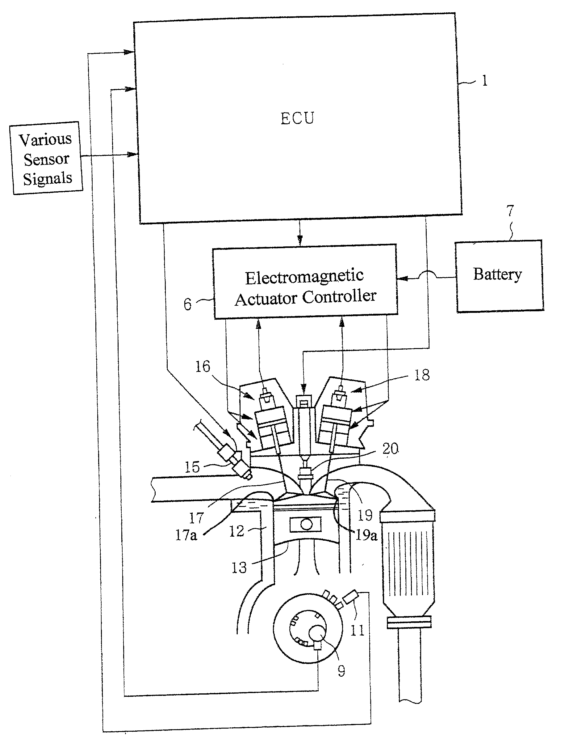
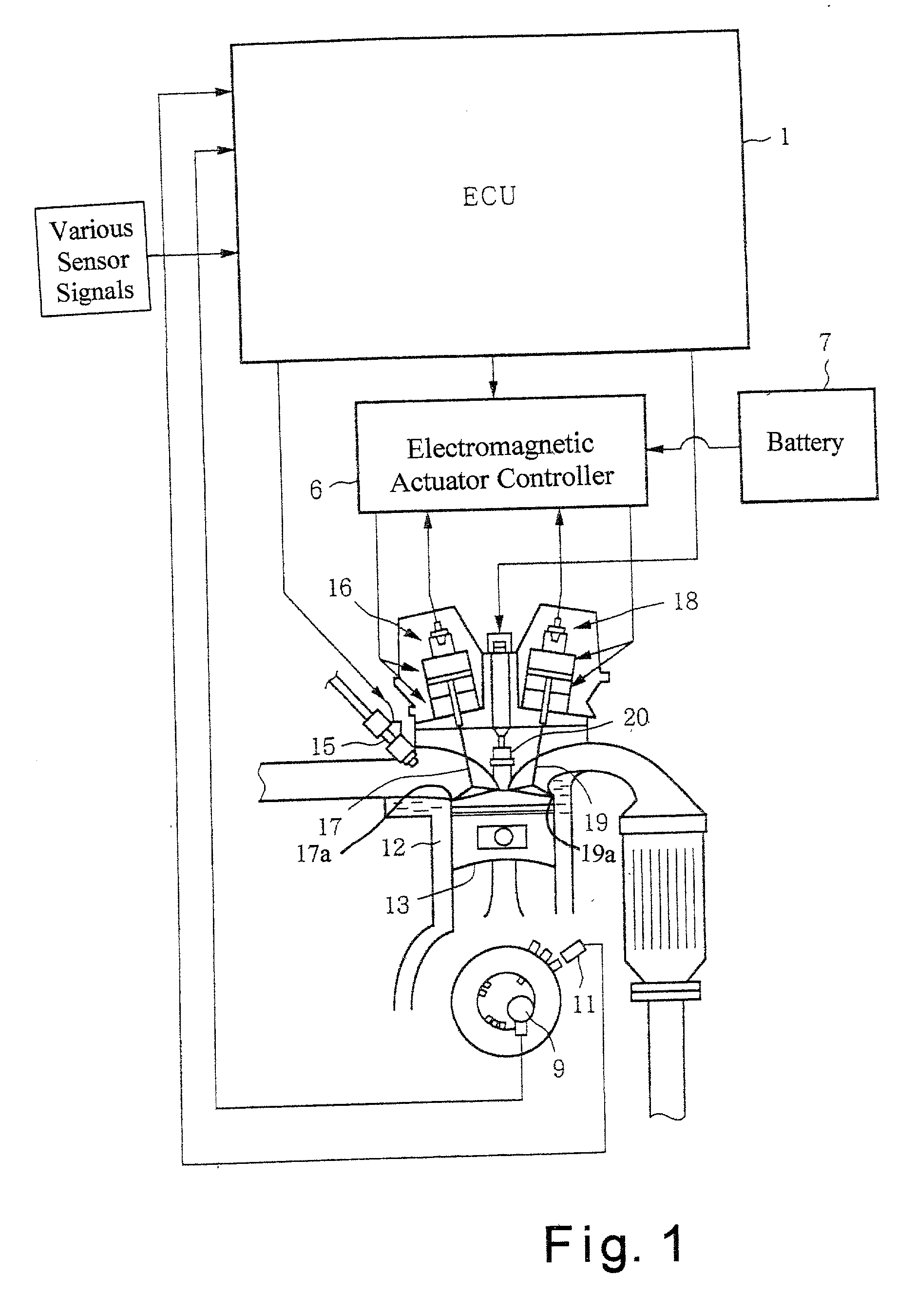
[0024] Referring initially to FIG. 1, an early closing Miller cycle internal combustion engine is diagrammatically illustrated to explain a first embodiment of the present invention. Basically, the early closing Miller cycle internal combustion engine embodiment of the present invention has an engine control unit 1 that controls an electromagnetic actuator controller 6 to open and close a plurality of intake valves 17 (only one shown) and a plurality of exhaust valve 19 (only one shown) by an intake valve driving actuator 16 and an exhaust valve driving actuator 18, respectively, such that the valv...


PUM


Abstract

The present invention mitigates restriction due to the fact that the opening period (angular working range) of the intake valve becomes smaller in the early closing Miller cycle operation, in which the intake valve closing timing occurs before the bottom dead center. The crankshaft center O1 is offset on one side from the cylinder central axis X. The top dead center and the bottom dead center of the piston occur when the three points, namely the crankshaft center O1, the crankpin center O2, and the piston pin center O3 are aligned in one line. At this time, the connecting rod and the crank arm are inclined relative to the axis X. The inclination angle .theta..sub.bdc at the bottom dead center is greater than the inclination angle .theta..sub.tdc at the top dead center. Therefore, as the crankshaft rotates in the direction of arrow .omega., the intake process and the expansion process become greater than 180.degree. CA, while the compression process and the exhaust process become smaller than 180.degree. crank angle. Accordingly, the angular working range of the intake valve is enlarged. Therefore, the restriction to the valve lift curve is mitigated.

Description

BACKGROUND OF THE INVENTION[0001] 1. Field of the Invention[0002] The present invention generally relates to an early closing Miller cycle internal combustion engine. More specifically, the present invention relates an early closing Miller cycle internal combustion engine, in which Miller cycle is achieved by advancing the angular timing of the closing of an intake valve relative to the intake bottom dead center.[0003] 2. Background Information[0004] A Miller cycle internal combustion engine has a greater expansion rate than compression rate in order to improve the fuel consumption rate. Thus, the Miller cycle internal combustion engine has recently been drawing more interest in the automotive field. Miller cycle internal combustion engines are broadly divided into late closing Miller cycle engines and early closing Miller cycle engines. In the late closing Miller cycle engines, the intake valve closing timing is delayed relative to the intake bottom dead center, such that the air t...

Claims


Application Information

Patent Timeline
Patent Type & Authority Applications(United States)
IPC IPC(8): F01L1/34F01L9/10F01L9/20F02D13/02F02D15/02
CPCF01L9/02F01L9/04F01L2001/0537F01L2800/00F02B2275/32F02D13/0207F02D13/0226F02D13/0253F02D13/0269Y02T10/142Y02T10/12F01L9/10F01L9/20
Inventor ARIGA, KENJI
Owner NISSAN MOTOR CO LTD
Why Eureka
Try Eureka