
Providing and using predefined part data for a CAD program

Inactive Publication Date: 2002-03-07
REDSPARK
View PDF1 Cites 15 Cited by
  • Summary
  • Abstract
  • Description
  • Claims
  • Application Information

AI Technical Summary

Benefits of technology

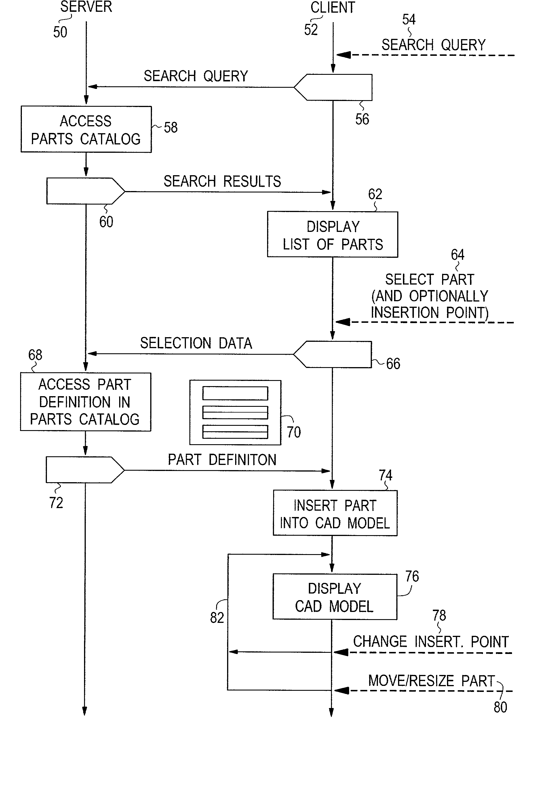
[0007] The invention provides and uses predefined part data that comprise a plurality of insertion point specifications, wherein each insertion point specification defines one possible way of inserting the predefined part into the CAD model with respect to both its location and its orientation. The invention provides the considerable advantage that exactly defined insertion points may be used by the designer for a wide variety of designs. The difficulties, errors, and inaccuracies associated with manual shifting and / or rotating operations are avoided, and both the quality of the finished CAD model and the efficiency of the design process are improved.
[0009] It is further preferred to provide functionality that allows the designer to define and / or change the size of the predefined part when inserting it into the CAD model. The selected insertion point preferably remains a fixed point, e.g. the center point of a linear stretching or compression operation when the size of the predefined part is defined and / or changed. This feature is especially useful because it allows quick adaption of a predefined part to the actual design requirements. Choosing a suitable insertion point in this case avoids the need for defining extensive auxiliary structures, which would have to be modified whenever the part is resized.

Problems solved by technology

Therefore, many manufacturers invest a considerable amount of time and effort in the development and distribution of electronic part definitions that match their actually sold parts and components.
However, the known techniques are less than perfect.
One problem is that, after inserting the predefined part into the CAD model, the designer must in many cases locate the part manually with respect to both its position and its orientation.
This process requires considerable time and effort and may even lead to design errors or to a lower accuracy of the finished CAD model.
The consequence of these difficulties may be that the acceptance of predefined parts is not as high as it could be, especially if the predefined part has a comparatively simple graphical representation that could also be created by the designer on the fly.

Method used


Image

  • Providing and using predefined part data for a CAD program
  • Providing and using predefined part data for a CAD program
  • Providing and using predefined part data for a CAD program

Examples


Embodiment Construction

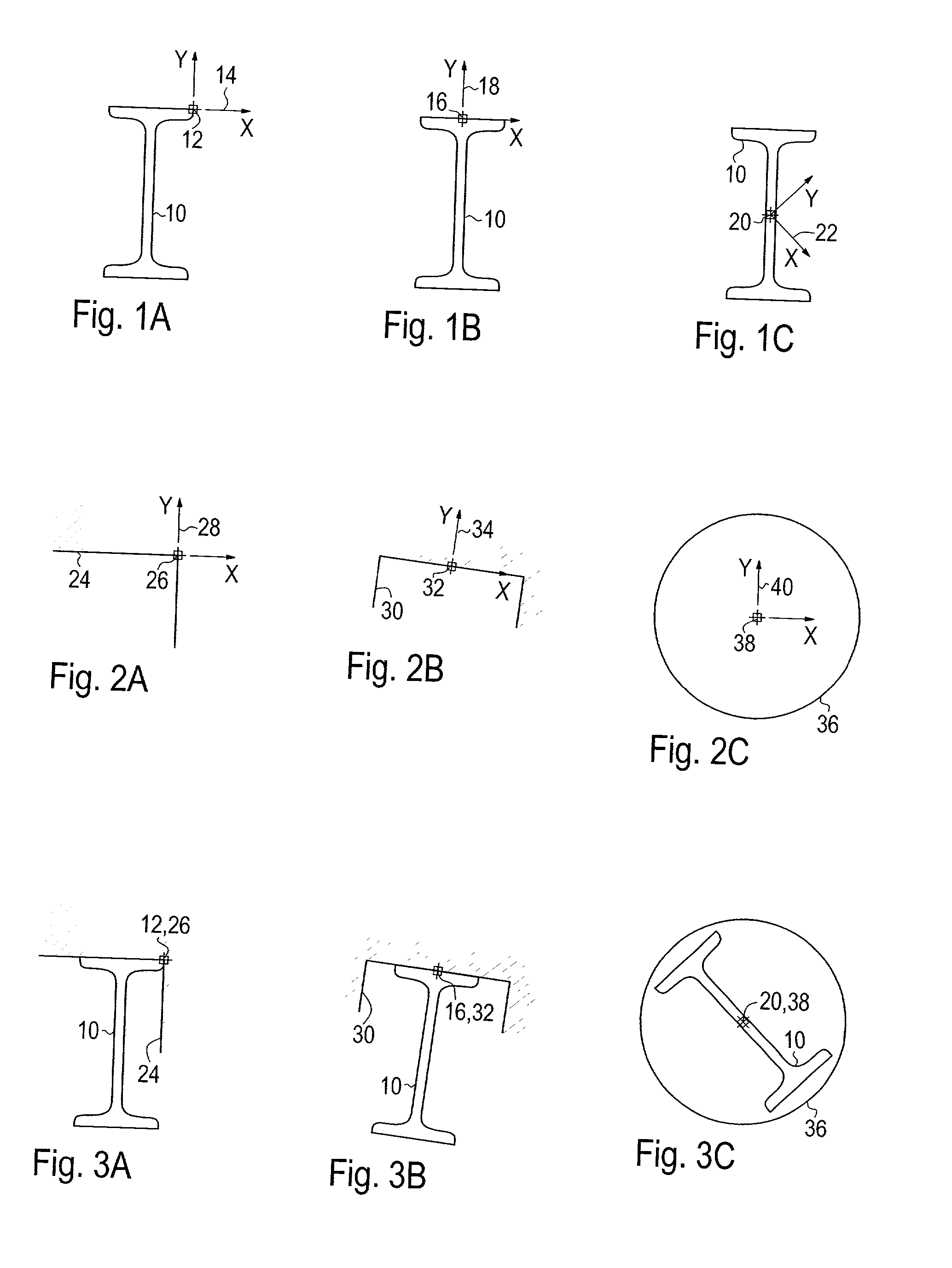
[0020] The predefined part 10 shown, as an example, in FIG. 1A-FIG. 1C is an I beam in a 2D representation and a direction of view along the main axis of the I beam. A first insertion point 12 is depicted in FIG. 1A at the rightmost end of the top face of the I beam. A first insertion coordinate system 14 has its origin at the first insertion point 12 and has an X axis that runs parallel to the top face of the I beam and a Y axis that runs normal thereto.

[0021] The first insertion point 12 is the default insertion point of the predefined part 10. However, according to the invention, the definition of the predefined part 10 comprises further predefined insertion points. FIG. 1B shows the part 10 with a second insertion point 16 positioned in the middle of the top face of the I beam and a second insertion coordinate system 18. FIG. 1C shows a third predefined insertion point 20 positioned in the center of the I beam and a third insertion coordinate system 22, which is oblique to the m...


PUM


Abstract

Providing And Using Predefined Part Data For A CAD Program A method for providing data (70) defining a predefined part for use in a CAD model processed by a CAD program is disclosed, in which the data (70) comprises a plurality of insertion point specifications (86, 88), where each insertion point specification (86, 88) defines one possible way of inserting said predefined part into said CAD model with respect to a location and an orientation of a said predefined part for insertion into said CAD model. A method for using such data (70) comprises corresponding features, and a CAD program and an apparatus employ the method for using such data (70). A computer readable data medium is characterized in that is contains such data (70). The invention provides a way of improving the usability of predefined parts for CAD models.

Description

FIELD OF THE INVENTION[0001] The invention relates to the field of computer aided design (CAD) and, in particular, to the field of using predefined part catalogs in connection with CAD techniques.DISCUSSION OF THE PRIOR ART[0002] The use of CAD techniques has become common engineering practice. Available CAD programs range from simple drawing tools to sophisticated systems covering the whole range of product design and possibly further aspects, such as engineering, manufacturing, and quality control. The term "CAD program" as used herein should therefore be understood in its broadest meaning as any computer program that contains a drawing and / or design component and possibly further components, and the term "CAD model" should be understood as any model or document processed by a CAD program. The word "part" is used to designate any object, element, or feature that is useful for designing a CAD model. While a part in this sense normally represents a tangible object, such as a motor o...

Claims


Application Information

Patent Timeline
IPC IPC(8): G06T19/00
CPCG06T19/00G06F17/5004G06F30/13
Inventor MULZER, MATTHIAS
Owner REDSPARK
Learn More