Phosphor for a plasma display device coated with a continuous thin protective layer and method of manufacture

a technology of phosphor and protective layer, applied in the field of phosphor, can solve the problems of reducing optical characteristics, affecting the practical use of the device, and reducing luminan

Inactive Publication Date: 2002-04-04
SAMSUNG SDI CO LTD
View PDF1 Cites 28 Cited by
  • Summary
  • Abstract
  • Description
  • Claims
  • Application Information

AI Technical Summary

Problems solved by technology

However, most protective coatings are particulate coatings in which a protective material is discontinuously deposited on the surface of the phosphor in the form of particles, but not in the form of a continuous film.
Such a particulate coating is known to greatly decrease the luminance.
Consequently, particulate coatings used at present do not satisfactorily serve as a protective layer and greatly decrease the optical characteristics so that their practical use is problematic.
However, these methods require a very sophisticated appar...

Method used


Image

  • Phosphor for a plasma display device coated with a continuous thin protective layer and method of manufacture
  • Phosphor for a plasma display device coated with a continuous thin protective layer and method of manufacture
  • Phosphor for a plasma display device coated with a continuous thin protective layer and method of manufacture

Examples


example 2

[0062] The phosphor was coated in the same manner as in Example 1, with the exception that the amount of TEOS was modified and the pH of the solution was set to 7.0. The amount of TEOS was modified such that the amount of the coating of SiO.sub.2 was adjusted to be 0.5, 1.0, 2.0, 4,0, 6.0, 8.0, and 10.0 wt % with respect to the weight of the phosphor.

[0063] FIG. 3 is a graph of the optical characteristic of the phosphors prepared in Example 2. FIG. 3 illustrates the optical characteristic, changes in the y-color coordinate and the luminescence efficiency according to the amount of the SiO.sub.2 coating, of the phosphors having a silica coating, in comparison with the optical characteristic of the phosphor not having a silica coating, after a heat deterioration test. As shown in FIG. 3, the luminescence efficiency varies depending on the amount of coating, but the y-color coordinate value is improved substantially. When considering the luminescence efficiency and the y-color coordina...

example 3

[0064] The phosphor was coated in the same manner as in Example 1, with the exception that the annealing temperature was modified to be 400, 600, 900, and 1200.degree. C. and the pH of the solution was set to 7.0.

[0065] FIG. 4 is a graph of the optical characteristic of the phosphors prepared in Example 3. FIG. 4 illustrates the optical characteristic, changes in the y-color coordinate and the luminescence efficiency according to the annealing temperature, of the phosphors having a silica coating, in comparison with the optical characteristic of the phosphor not having a silica coating, after a heat deterioration test. As shown in FIG. 4, the higher the annealing temperature, the better the y-color coordinate value and the worse the luminescence efficiency. But, when these two facts are considered, it can be seen that the optimal annealing temperature is about 900.degree. C.

example 4

[0066] The phosphor coated with alumina was manufactured in the same manner as in Example 1, with the exception that 7.5 g of aluminum sec-butoxide was used instead of 12 g of TEOS, the annealing temperature was 800.degree. C., and the pH of the solution was adjusted to 0.5, 2.0, 3.5, 5.0, and 6.5 using nitric acid instead of acetic acid.

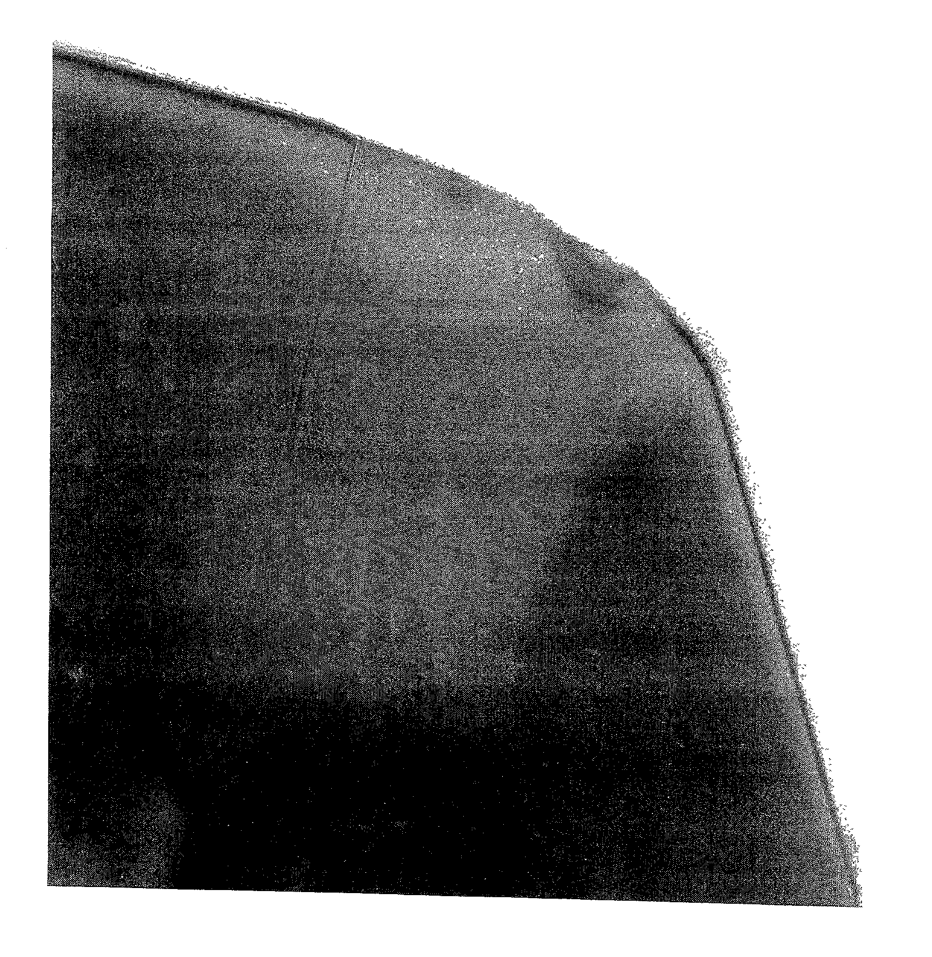
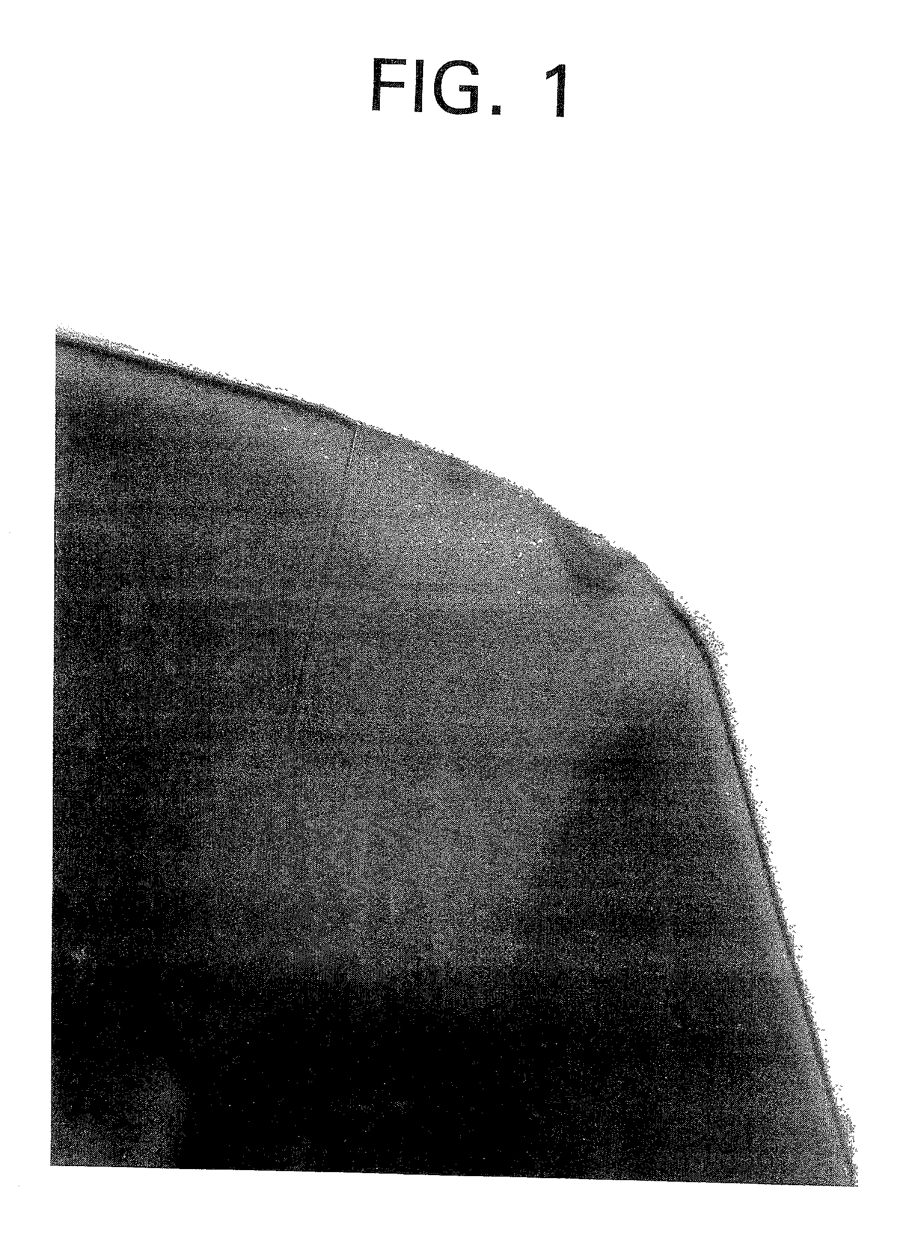
[0067] FIG. 5 is a TEM analysis photograph of the phosphor coated at a pH of 2.0. The darker portion denotes the phosphor particle. It was confirmed that a continuous, thin film coating of Al.sub.2O.sub.3 was formed on the surface of the phosphor particle. The thickness of the coating was about 5-10 nm.

[0068] FIG. 6 is a graph of the optical characteristic of the phosphors prepared in Example 4. FIG. 6 illustrates the optical characteristic, changes in the y-color coordinate and the luminescence efficiency according to pH, of the phosphors having an alumina coating, in comparison with the optical characteristic of the phosphor not having an alumina ...


PUM

PropertyMeasurementUnit
Thicknessaaaaaaaaaa
Temperatureaaaaaaaaaa
Thicknessaaaaaaaaaa

Abstract

Phosphor coated with wide bandgap metal oxide which can be used for a plasma display panel (PDP) has a surface that is coated with a continuous, thin film of wide bandgap metal oxide. In preparing the phosphor coated with wide bandgap metal oxide, a pH of the wide bandgap metal oxide precursor solution containing an organic solvent and water is adjusted to 0.1-10 and heated under a reflux, thereby obtaining a metal hydroxide gel. The wide bandgap metal hydroxide gel is made to contact a phosphor for a PDP, thereby obtaining the gel-coated phosphor. The gel-coated phosphor is then dried and sintered.

Description

[0001] This application claims the benefit of Korean Application No. 2000-57339, filed Sep. 29, 2000, in the Korean Industrial Property Office, the disclosure of which is incorporated herein by reference.[0002] 1. Field of the Invention[0003] The present invention relates to a phosphor which is coated with a protective layer and which can be used for a plasma display panel (PDP), and more particularly, to a phosphor used for a PDP and coated with a continuous, thin protective layer, thereby improving the optical characteristics and the lifetime of the PDP.[0004] 2. Description of the Related Art[0005] Since a PDP self-radiates on a similar principle to a fluorescent lamp, an image shown on the PDP has a uniform brightness, a relatively high contrast, and a viewing angle greater than 160 degrees even if a screen of a PDP is large. The PDP is known to best display a large screen of 42-60 inches. In addition, a PDP has upper and lower glass plates and a thickness no greater than 10 cm ...

Claims


Application Information

Patent Timeline
IPC IPC(8): H01J17/49C09K11/02C09K11/77
CPCC09K11/025Y10S428/917C09K11/7734H01J11/42H01J11/40
Inventor DO, YOUNG-RAGPARK, DO-HYUNGKIM, YONG-SEON
Owner SAMSUNG SDI CO LTD
Why Eureka
Try Eureka