Compact hydraulically-operated derailleur shifting system for bicycles

a hydraulically operated, bicycle technology, applied in cycle equipment, transportation and packaging, gearing, etc., can solve the problems of affecting the precision of the derailleur, difficult shifting of the derailleur, and affecting the accuracy of the derailleur

Inactive Publication Date: 2002-05-16
PATTERSON RICHARD A +1
View PDF0 Cites 17 Cited by
  • Summary
  • Abstract
  • Description
  • Claims
  • Application Information

AI Technical Summary

Problems solved by technology

Unfortunately, the front and rear chain shifting systems have remained essentially unchanged; and still use mechanical cables to control the chain guiding mechanisms.
However, when mountain bikes are used in the dusty, wet, and muddy conditions found on rugged and primitive roads and trails, various contaminants work their way into the derailleur's pivots and open linkages as well as into and under tension control cables.
Such contamination makes the derailleurs difficult to shift, adversely affects their precision in shifting, and also makes them wear out very quickly.
Under extremely harsh operating conditions, existing mechanical derailleurs will fail, making it impossible for the cyclist to change drive ratios.
Rubber covers or boots provide some protection for the parallel linkages on the front and rear derailleur mechanisms, but these covers are not waterproof, and mud and water can still enter the mechanisms.
However, dirt can still enter these control cables and cause the cables to stick or bind inside their flexible guide housings.
While hydraulic shif

Method used


Image

  • Compact hydraulically-operated derailleur shifting system for bicycles
  • Compact hydraulically-operated derailleur shifting system for bicycles
  • Compact hydraulically-operated derailleur shifting system for bicycles

Examples


Embodiment Construction

)

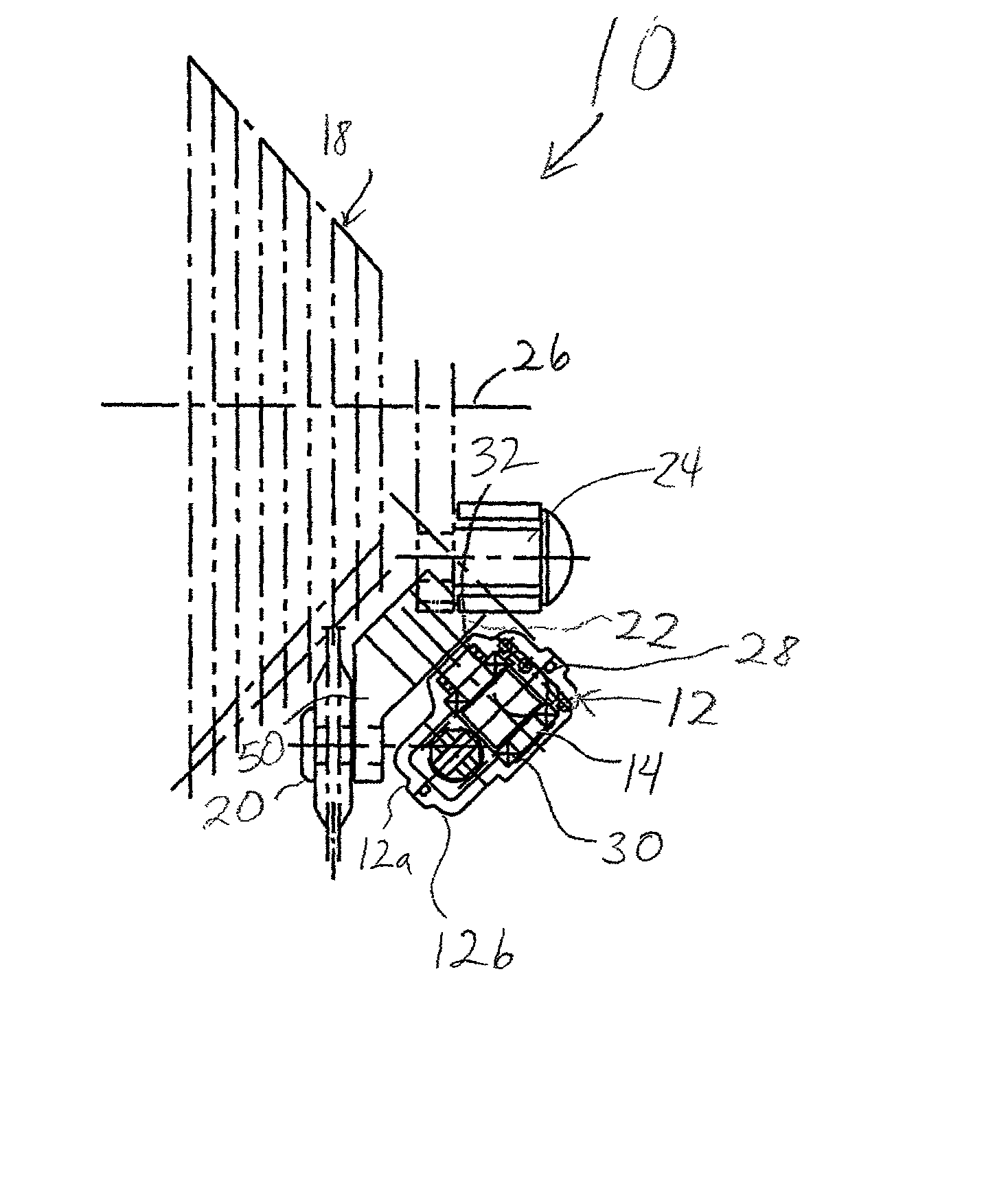
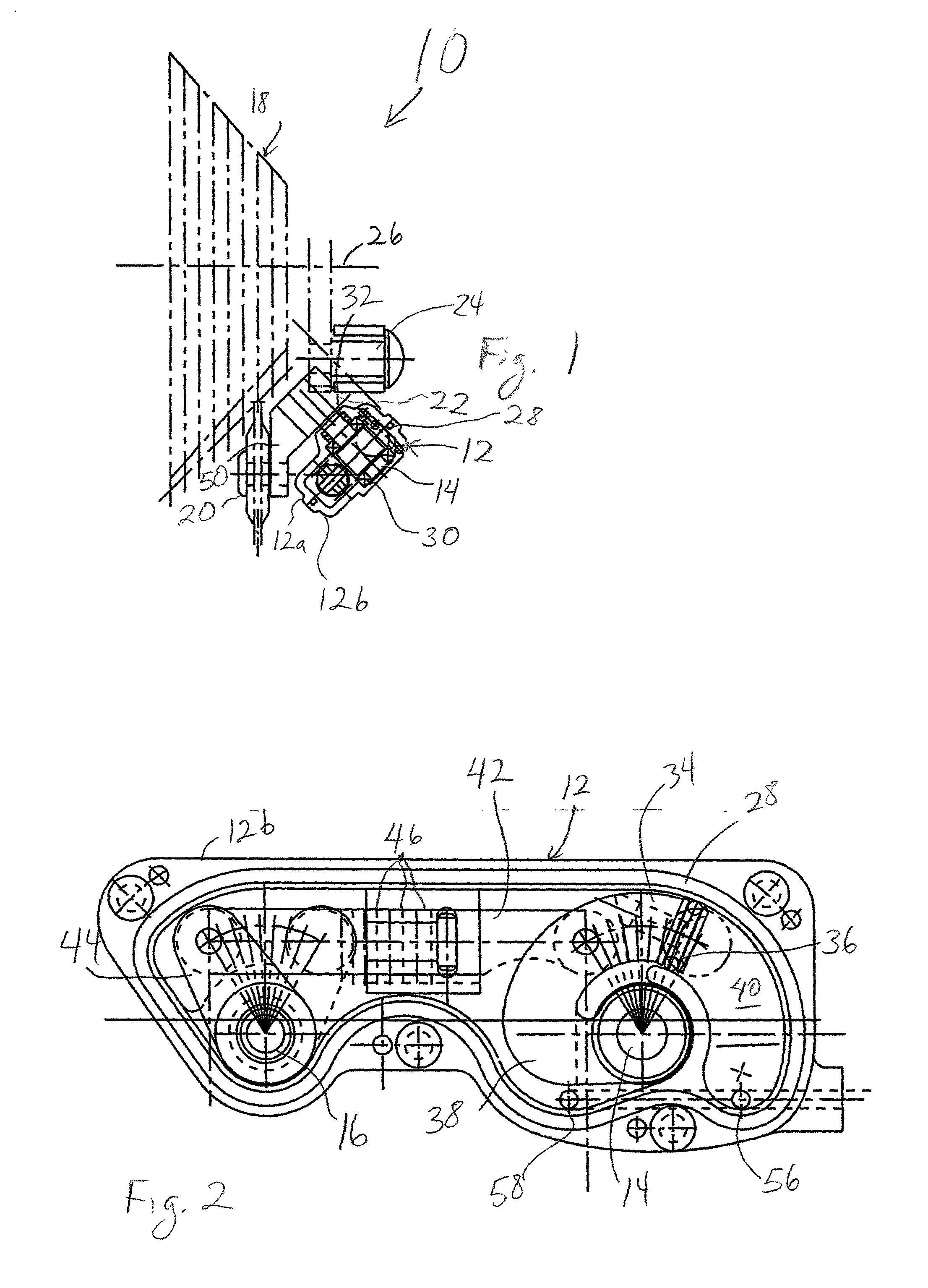
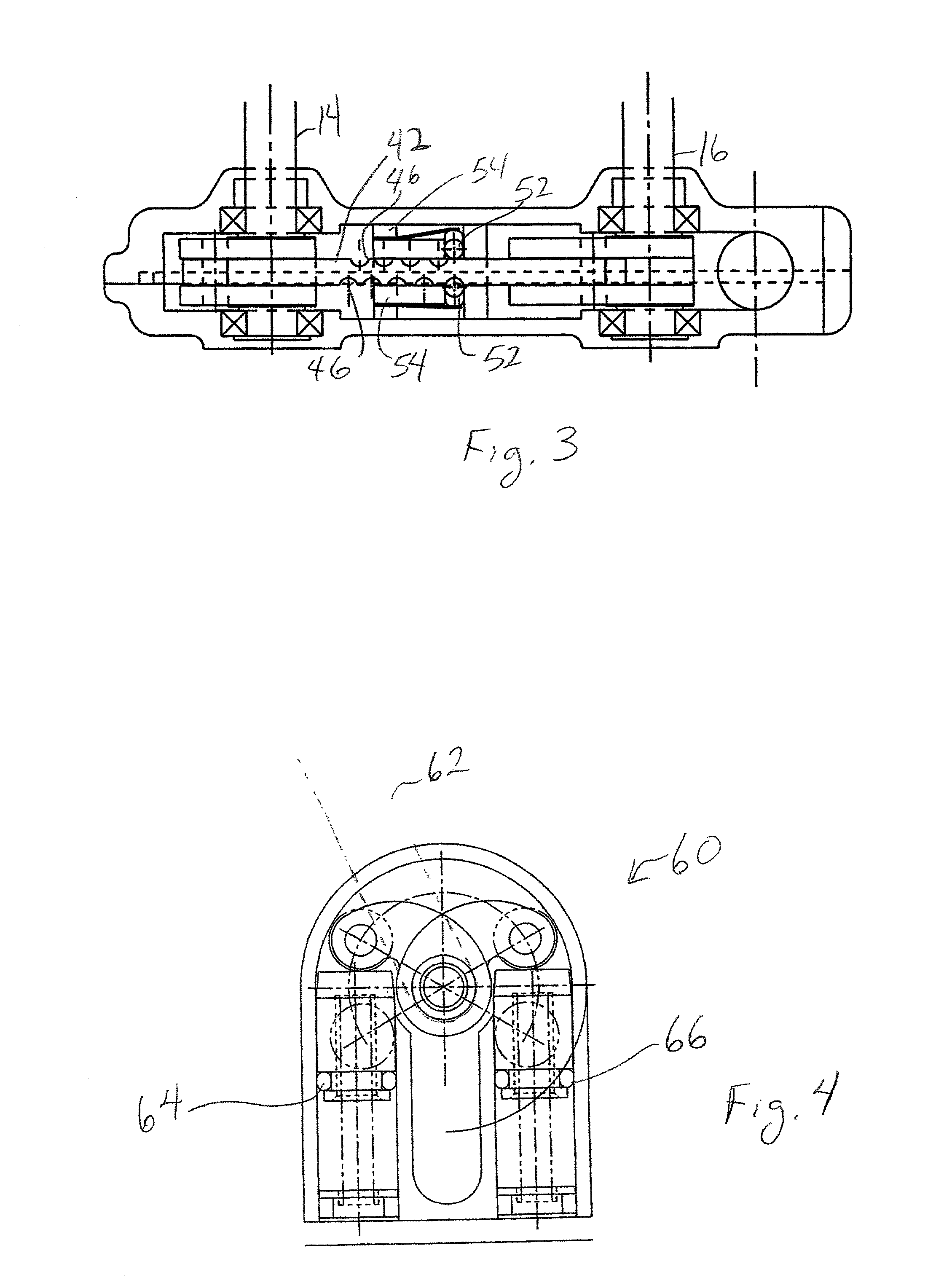
[0024] The present invention is directed to a compact, hydraulically-operated rear derailleur shifting system for mountain, road and tandem bicycles. The shifting systems described herein are improvements over the designs disclosed in U.S. patent application Ser. No. 09 / 519,200, and U.S. Pat. Nos. 6,042,495 and 6,012,999, each of which is hereby incorporated.

[0025] The hydraulic shifting systems described in foregoing patents have a number of advantages over cable-operated mechanical shifting systems, especially when these systems are operated in harsh conditions. These conditions could occur on wet, muddy, dusty, or sandy environments and trials that are likely to be experienced where mountain bikes are commonly used. Mud, sand, water, and dust / dirt are especially harmful to the small exposed mechanisms in existing cable operated shifting systems. Equally vulnerable to these conditions is the exposed, unsealed mechanical pull cable that conveys shifting signals from the mechanical...


PUM


Abstract

A derailleur utilizes a 4-bar linkage, including a housing which acts as one bar of the 4-bar linkage. A hydraulic assembly located within the housing moves the housing relative to the mounting shaft in response to hydraulic pressure to define a chain guide operating path. The derailleur device may include a detent mechanism formed on one of the three other bars. In one embodiment, the 4-bar linkage includes an input shaft rotatably attached to the housing at a one end, and an output shaft rotatably attached to the housing at the other end, and the housing rotates around the first shaft in response to the actuation force. The hydraulic assembly may include a piston which moves within a cylindrical bore, with one of the three other bars of the 4-bar linkage being attached to the piston. The resulting hydraulic derailleur design is comparable to mechanical (cable-pull type) derailleurs in size and weight.

Description

[0001] This application is a continuation-in-part of copending U.S. patent application Ser. No. 09 / 519,200 filed on Mar. 6, 2000, which is a continuation of U.S. patent application Ser. No. 09 / 137,219 filed on Aug. 20, 1998, now U.S. Pat. No. 6,042,495, which is a continuation-in-part of U.S. patent application Ser. No. 08 / 997,973 filed Dec. 24, 1997, now U.S. Pat. No. 6,012,999.[0002] 1. Field of the Invention[0003] The present invention generally relates to bicycles, and more specifically to hydraulically-operated control systems for bicycles, particularly shifting systems for bicycles which use a derailleur or similar chain guide to control the position of the drive chain.[0004] 2. Description of the Related Art[0005] Typical bicycles can be operated in multiple gears by adjusting a drive chain between a cluster of larger diameter sprockets on the pedal crankshaft and a sprocket cassette mounted on the rear wheel axle. A device known as a derailleur is used to position the drive ...

Claims


Application Information

Patent Timeline
IPC IPC(8): B62M9/122B62M9/1244B62M25/08F16H7/08
CPCB62M9/122F16H2007/0859B62M25/08
Inventor PATTERSON, RICHARD A.PATTERSON, ROY M.
Owner PATTERSON RICHARD A
Why Eureka
Try Eureka