System and method for metalization of deep vias

a metalization system and metalization technology, applied in the direction of printed element electric connection formation, conductive pattern formation, coating, etc., can solve the problems of preventing sufficient electrical contact and sometimes any contact with the imbedded layer, affecting the quality of the imbedded layer, and increasing the cost of components

Inactive Publication Date: 2002-06-06
EXCELLON AUTOMATION
View PDF0 Cites 33 Cited by
  • Summary
  • Abstract
  • Description
  • Claims
  • Application Information

AI Technical Summary

Benefits of technology

[0014] This is advantageous in that the PCB being worked remains in the registration position and the system knows the precise location of each of the drilled holes and their characteristics including, in particular, their depth.
[0017] In either case, since the blind vias are injected by needle, the tip thereof is positioned at the bottom of the via regardless of depth, and thus eliminates the bubble which is pushed away from the bottom by the injected epoxy.
[0019] The present invention allows for high aspect ratio blind vias to reach deep within the printed circuit board, eliminating the need for much of the threading of circuits up through the multilayer. This lessens the complication of the inner layers and provides more real estate for other uses and functions.

Problems solved by technology

However, where blind vias are to be plated, and in particular, deep blind vias having aspect ratios of greater than 1.2, use of the squeegee method causes bubbles to be formed at the bottom of the blind via thereby preventing sufficient electrical contact and sometimes any contact at all with the imbedded layer.
Because present technology and practices do not allow high aspect ratio blind vias to be adequately metalized or plated, many added circuits are threaded throughout the multilayer circuit boards to bring discreet circuits near an outside surface of the board so that current low aspect ratio holes can make the connections necessary between circuits.
However, the method is not a positive one in that bubbles are nevertheless formed and while the pin modification may be able to correct this bubble formation, it does not prevent it.
In addition, special circuit board components are fabricated to implement this correction problem and make the components more expensive, in addition to requiring increased inventory to carry both conductive epoxy components and standard fabrication components.
While the air bubble is one problem that prevents the fluid epoxy from completely filling the hole, there are other problems.
For one, there is the inability to completely remove fluid from the deep vias.
In the plating process, the circuit boards go through a number of acid and rinse baths and if there is any fluid retained in the hole by surface tension or capillary action, such fluid may damage the solution used the next one, two or three or more baths and prevent adequate plating.
Another problem is the inability to replace the depleted fluid in a deep hole.
A further problem is that holes may blind over or seal themselves with plating material at the top before the bottom or sides of the hole are plated.

Method used


Image

  • System and method for metalization of deep vias
  • System and method for metalization of deep vias
  • System and method for metalization of deep vias

Examples


Embodiment Construction

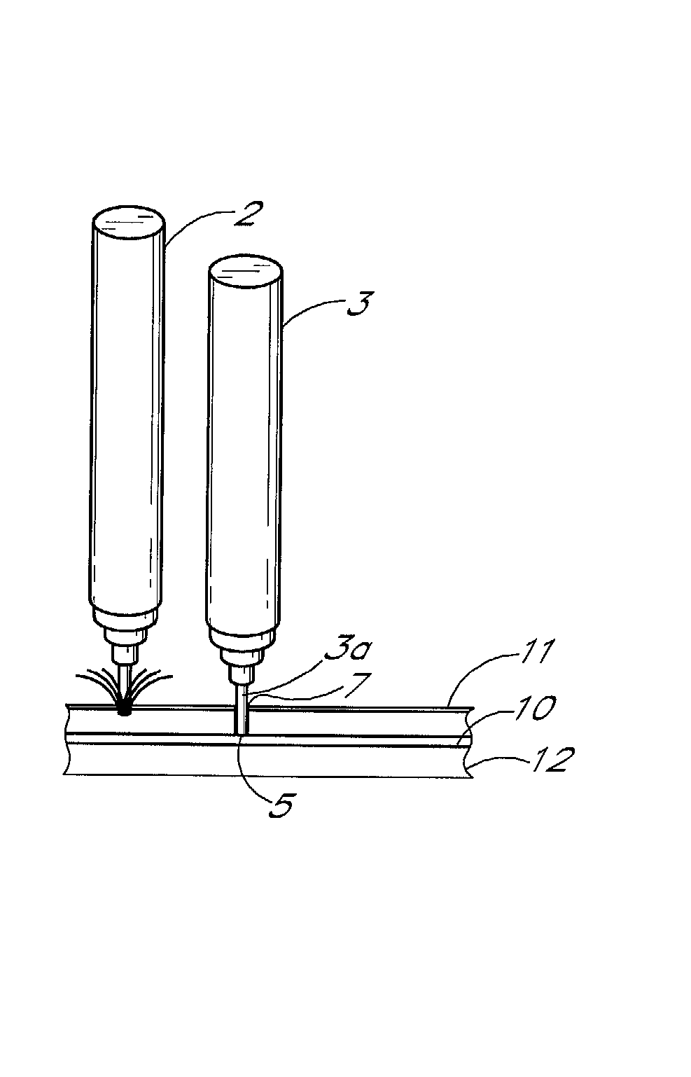
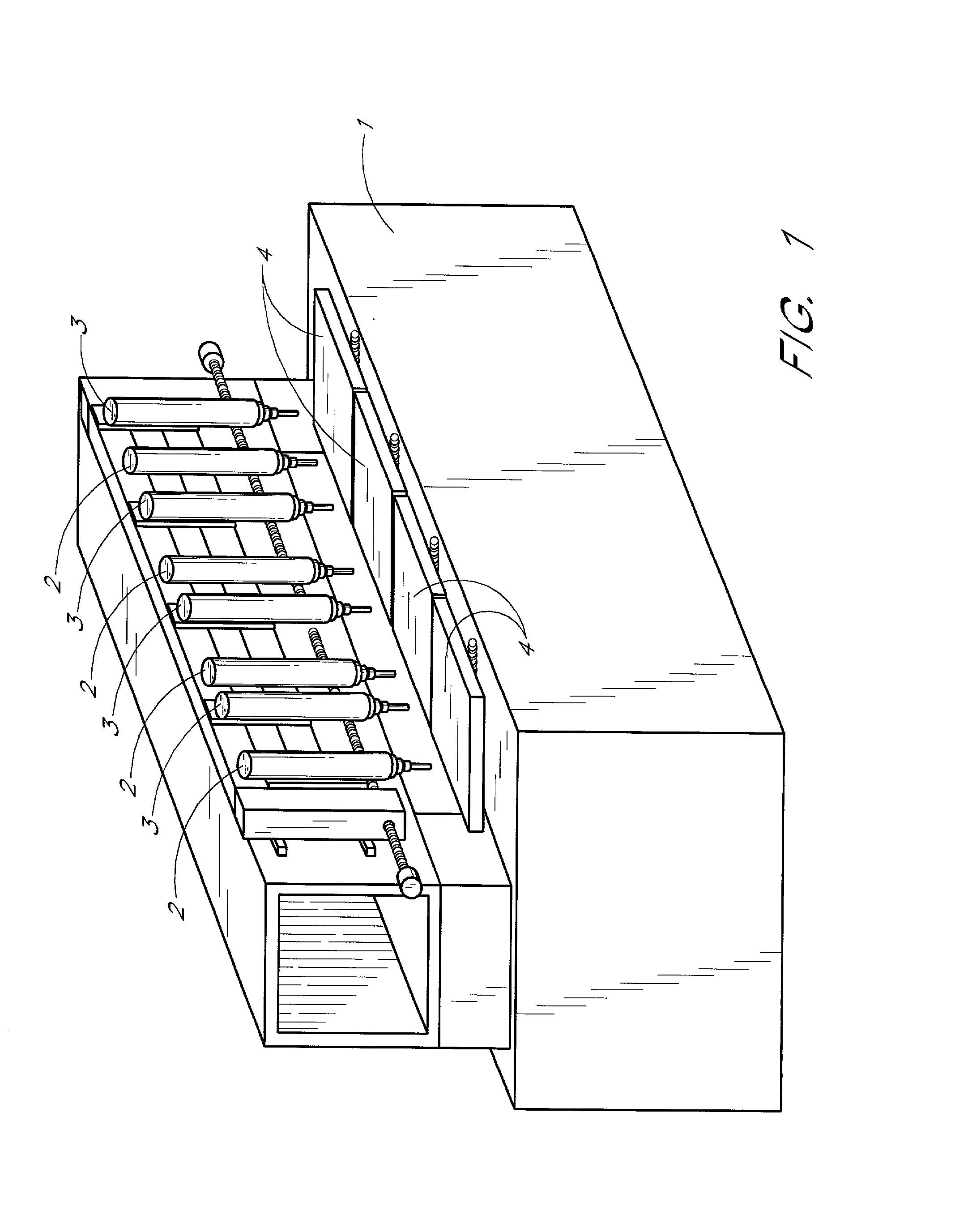
[0027] Referring now to the drawings, FIG. 1 shows a typical machine tool which has a plurality of spindles 2 having tools 2a mounted thereon. Individual ones of said spindles are positioned over each of a plurality of worktables 4. Each of the spindles 2 is accompanied by an epoxy injector 3 which comprises a hollow injector needle 3a and an epoxy reservoir 3b for carrying a supply of conductive epoxy 5. The needle may have holes in the sides thereof as well. A compression system not shown applies pressure through a hose 3c and fitting 3d to the epoxy reservoir 3b to force measured amounts of conductive epoxy through the needle and into a workpiece mounted on the worktable 4. The diameter of the hollow injector needle 3a is equal to or smaller than the diameter of the drilled hole.

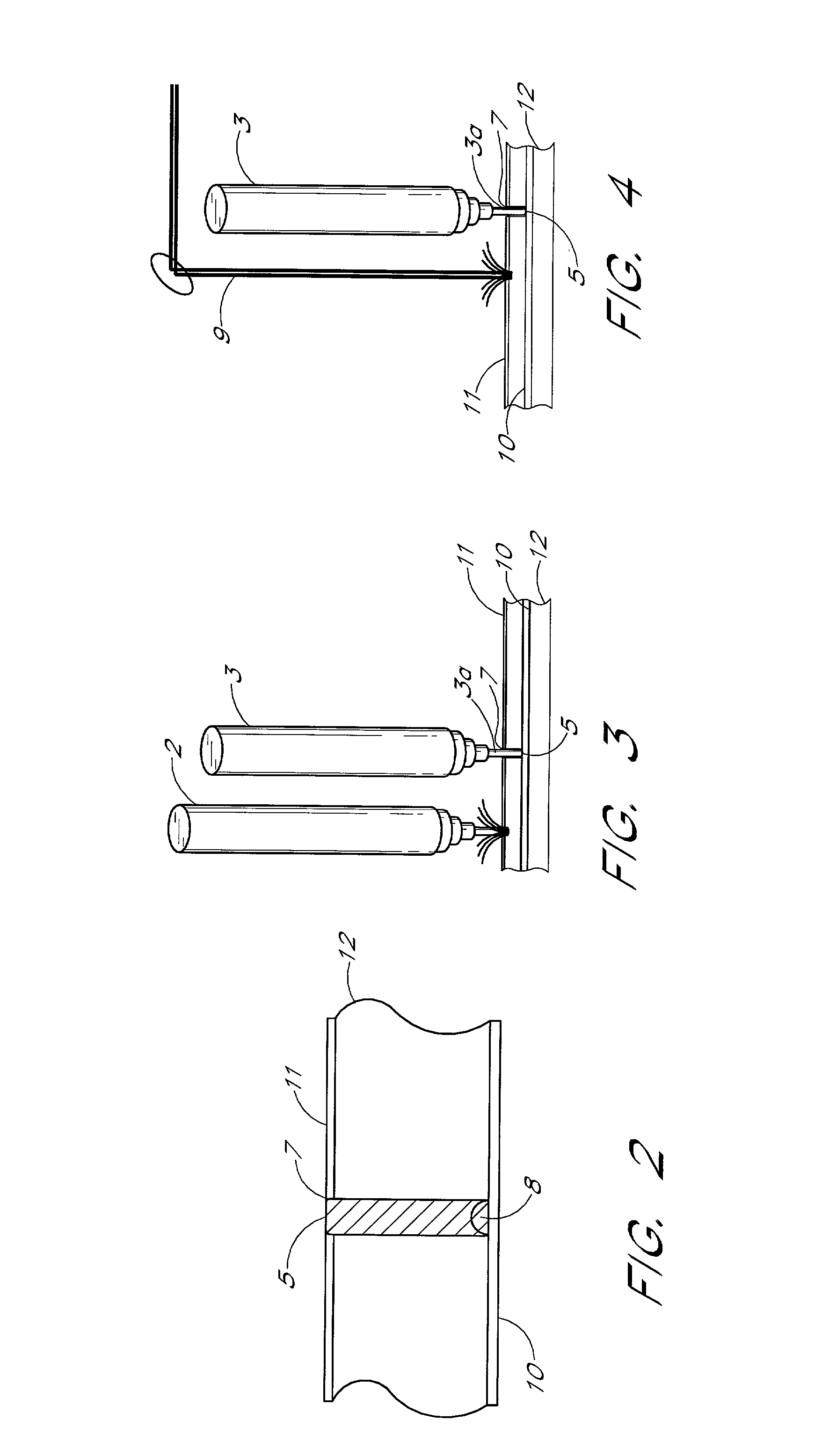
[0028] Referring now to FIG. 2, the prior art method of filling routed channels is not satisfactory for filling holes 7 in a PCB 12 with electrically conductive epoxy 5 because using the squeegee method r...


PUM

PropertyMeasurementUnit
aspect ratioaaaaaaaaaa
aspect ratiosaaaaaaaaaa
conductiveaaaaaaaaaa

Abstract

In a method of injecting an electrically conductive epoxy into blind vias during drilling or shortly thereafter in order to avoid oxidation of the copper or other metal of the imbedded layer, a machine tool is provided with at least one controllable spindle and at least one injection device. Alternatively, two machine tools, one with at least one controllable spindle and one with at least one injection device, may be provided. A printed circuit board mounted on the machine tool table for drilling is registered in the usual way for the particular machine tool. The machine tool part program then drills a particular pattern for the circuit board for mounting of circuit board components. All of the blind vias as well as through hole vias are drilled at one time by the machine tool by the tools mounted in the spindle or by laser drilling systems, but may also be drilled and filled in any sequence. The drilling operation is followed by the epoxy injecting operation in which a controlled operating device, comprising a reservoir, a pumping mechanism, a hollow needle through which the conductive epoxy flows to the bottom of the hole, a control mechanism, and sensors detect various mechanism operations and when hole fill is completed.

Description

[0001] 1. Field of the Invention[0002] The field of this invention relates generally to drilling and metalization of printed circuit boards. More particularly, the field of this invention relates to enhanced metalization of deep vias.[0003] 2. Related Art[0004] Machine tools have been used to drill holes through printed circuit boards for many years. Subsequent to the drilling of such holes, interhole plating or metalizing is required to ensure appropriate electrical connection. Such metalization systems include the electrical explosive techniques, and other generally-known metalization methods. Often, such circuit boards are multilayered, which require holes to be drilled to a layer within the circuit board instead of through the board. These holes are called blind vias because they terminate at one end.[0005] Plating differs from through holes in that the blind vias are limited in depth, generally, to an aspect ratio of 1 to 1.2, in order to ensure that adequate plating can take p...

Claims


Application Information

Patent Timeline
Patent Type & Authority Applications(United States)
IPC IPC(8): H05K3/00H05K3/40
CPCH05K3/0035H05K3/0047H05K3/4069H05K2201/0919Y10T29/49165H05K2203/0126H05K2203/0207H05K2203/163Y10T29/49155H05K2201/09518
Inventor HALL, HENDLEY W.FINN, WAYNE K.
Owner EXCELLON AUTOMATION
Why Eureka
Try Eureka