Method and apparatus for reducing motion artifacts and noise in video image processing

a technology of motion artifacts and video image processing, applied in the field of reducing motion artifacts and noise in video image processing, can solve the problems of undetectable reduction of the clarity of moving images, inability to distinguish between noise, etc., and achieve the effect of reducing or minimal filtering and reducing motion artifacts

Inactive Publication Date: 2002-06-20
GE MEDICAL SYST GLOBAL TECH CO LLC
View PDF0 Cites 22 Cited by
  • Summary
  • Abstract
  • Description
  • Claims
  • Application Information

AI Technical Summary

Benefits of technology

[0007] It is an object of the present invention to provide a method and apparatus for obtaining improved video images with reduced motion artifacts and reduced noise.
[0008] It is another object of the invention to provide a method and apparatus for decreasing the amount an image is filtered when the image is moving or a portion of the image is moving. Reducing the temporal filtering when the image is moving reduces the smearing or blurring in the moving portion of the image and maintains good noise filtering of the non-moving portion of the image.
[0009] It is another object of the invention to provide such a method and apparatus for maximizing filtering of noise from stationary images or portions of an image.
[0023] FIG. 2 illustrates a block diagram of a pixel filtering model for reducing noise and motion artifacts in each pixel of a video image the motion value also controls the filtering functions with spatial filter values available to be used as an input to the temporal filter, and this control is based on the motion value control signal;

Problems solved by technology

The drawback of simple temporal filters is that they are unable to distinguish between noise and motion in a live image, so filtering occurs whether the changes in pixel difference values are caused by undesirable noise or acceptable motion.
Thus, in an effort to reduce noise, temporal filters undesirably reduce the clarity of moving images.

Method used


Image

  • Method and apparatus for reducing motion artifacts and noise in video image processing
  • Method and apparatus for reducing motion artifacts and noise in video image processing
  • Method and apparatus for reducing motion artifacts and noise in video image processing

Examples


Embodiment Construction

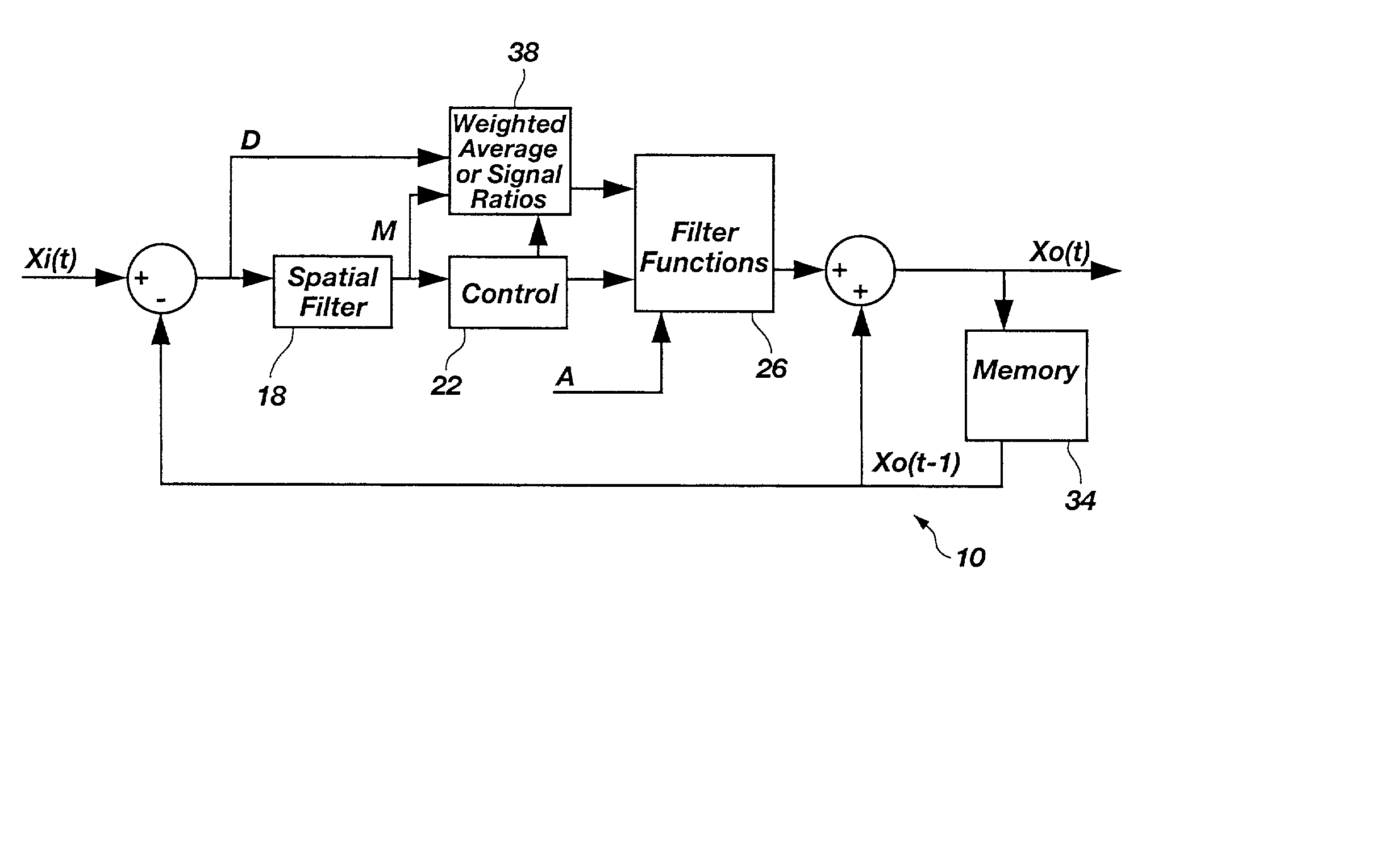
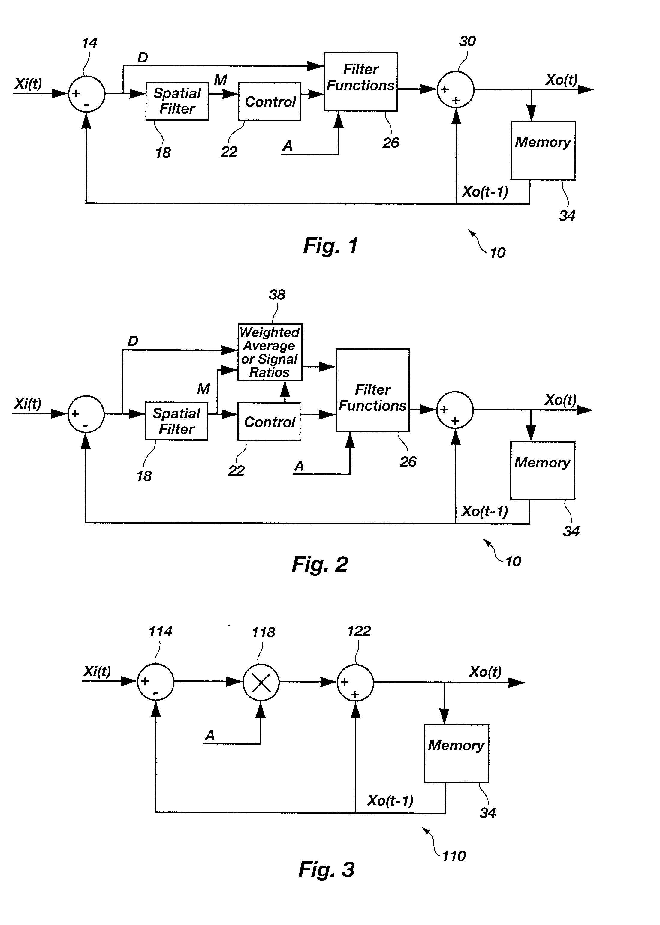
[0036] FIG. 1 illustrates a block diagram of a temporal pixel filtering model of a video image filter 10 for reducing noise and motion artifacts in each pixel of each frame in a video image. The pixel values for an incoming image frame are represented by Xi(t) while the pixel values for an output image frame are represented by Xo(t). Chronologically, Xi(t) represents pixels of a frame in the video image prior to filtering and Xo(t) represents the pixel values in the same frame after being filtered. The symbol Xo(t-1) represents the immediately previously displayed pixel values, i.e., the most recently stored pixel values that were obtained from the previous filtering process. When pixel values Xi(t) of a frame of the most recently acquired values are supplied to the video image filter 10, a subtractor 14 calculates the difference between the pixel input values Xi(t) and the most recently stored pixel values Xo(t-1) to obtain pixel difference values "D" for each of the pixels in the ...


PUM


Abstract

A method and apparatus for reducing noise and motion artifacts in pixels of a processed or displayed video image by filtering pixel values of the video image based on a first frame having currently stored (filtered) pixel values and a second frame having recently captured but not yet filtered pixel values. The apparatus includes a spatial filter for computing a motion value of a pixel of interest by averaging difference values of selected pixels surrounding the pixel of interest. Also included is a filter function means for producing an output difference value of the pixel of interest based on the motion value and an adder for adding the output difference value to the first frame filtered pixel value of the pixel of interest. Thus, each pixel of the video image is filtered according to the amount of motion in the video image.

Description

[0001] 1. The Field of the Invention[0002] This invention relates generally to reducing motion artifacts and noise in video image processing, and more particularly, to a method and apparatus by which video images are filtered on a per pixel basis over time, from frame to frame.[0003] 2. The Background Art[0004] It is known in the art to reduce noise in video images by filtering digital data (that represents each frame of the video images) with a temporal filter (also known as a "recursive filter"). A temporal filter can be realized through hardware or software, with hardware realizations commonly implementing multiplier or a look up table for holding the data representative of the gain coefficients of pixel difference values. Pixel difference values are the difference between a pixel value from one frame to the next, the pixel value being a set of bits from the digital data of one frame. A temporal filter performs noise reduction by operating on each single pixel in the frame or arr...

Claims


Application Information

Patent Timeline
Patent Type & Authority Applications(United States)
IPC IPC(8): G06T5/00G09G5/00G09G5/36H04N5/14H04N5/21
CPCH04N5/21
Inventor ALLRED, JOSEPHANDERTON, R. LARRYCURTIS, STEVENHANOVER, BARRY K.
Owner GE MEDICAL SYST GLOBAL TECH CO LLC
Why Eureka
Try Eureka