Method and apparatus for reducing the flow of RF noise from subscriber's premise cable systems into the reverse transmission path of two-way cable networks

Inactive Publication Date: 2002-06-27
MCNAMARA ROBERT
View PDF2 Cites 21 Cited by
  • Summary
  • Abstract
  • Description
  • Claims
  • Application Information

AI Technical Summary

Problems solved by technology

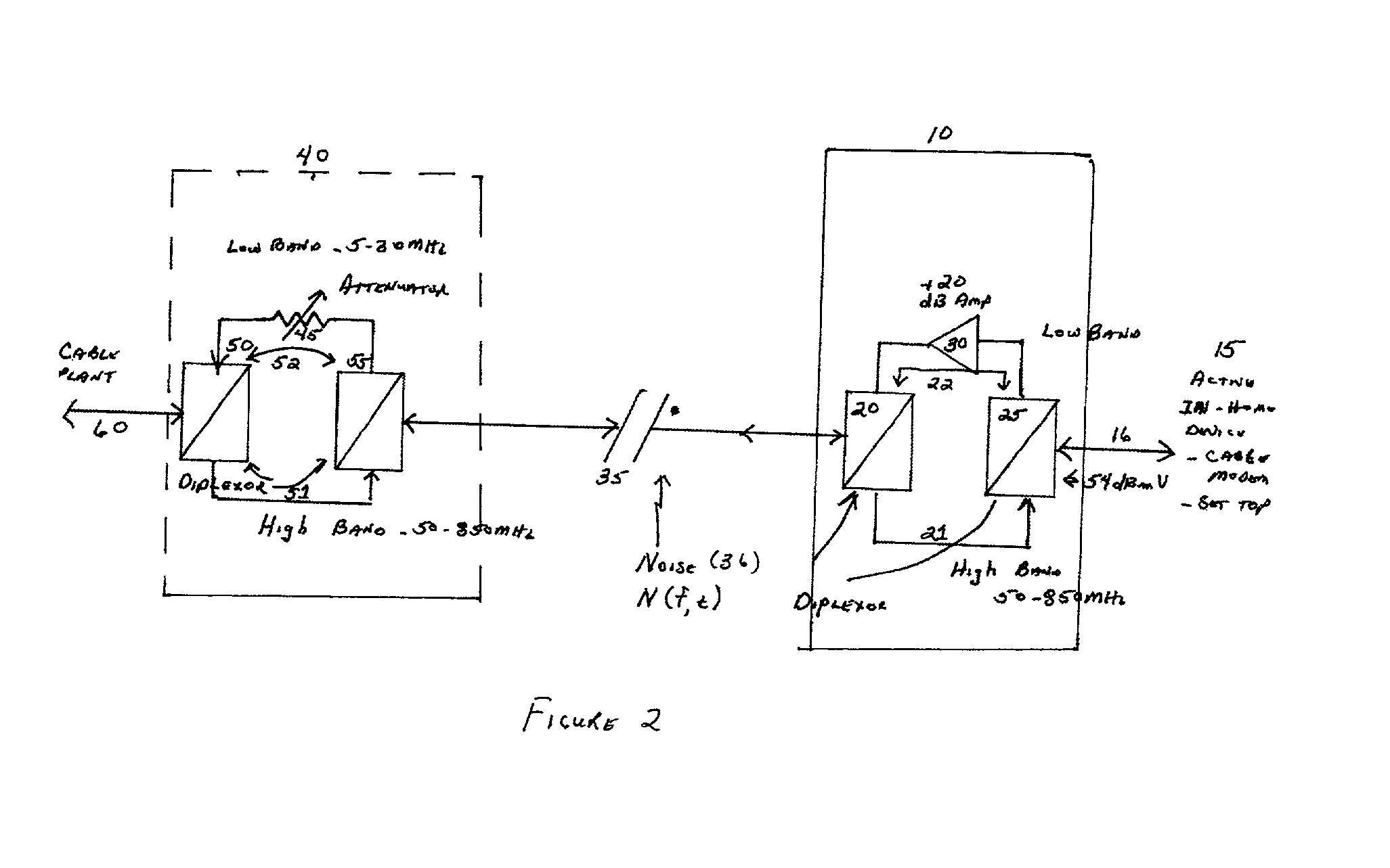
The problem that cable system operators face today is that the low band RF spectrum is highly susceptible to leakage of unwanted stray signals and RF interference from a variety of sources (collectively labeled "Ingress Noise").
In a worst case situation, no usable return signals may be received from a particular fiber node and all two-way communications capability is lost.
The reason that Ingress Noise in the return RF band is the dominant problem facing network operators is two-fold.
First, use of the lower portion of the RF spectrum of a cable system (5-30 / 42 MHz) for return path transmissions has one serious side effect, the outer conductor of the coaxial cable does not shield as effectively in this low band as it does at higher frequencies.
Stated another way, at lower frequencies the cable's shielding is more ineffective and more susceptible to picking up unwanted signals than at higher frequencies.
However, in the return path, the effect of high levels of RF noise and ingress is to lower CNR levels of the return RF signals and may seriously damage or destroy the ability of NIUs to communicate or, in the case of spread spectrum technology, drastically slow down network performance.
Unfortunately, there are several other transmission impediments that also degrade the reverse path performance and exacerbate the effects of stray and interfering carriers on the upstream RF spectrum.
However, the reverse path of most cable systems today is not engineered to support unity gain.
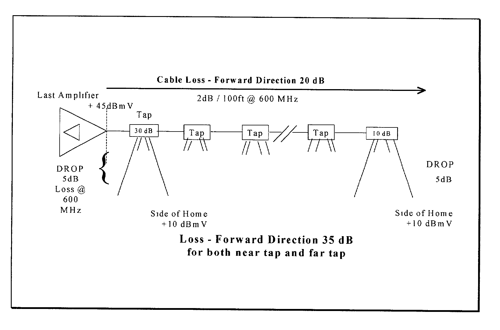
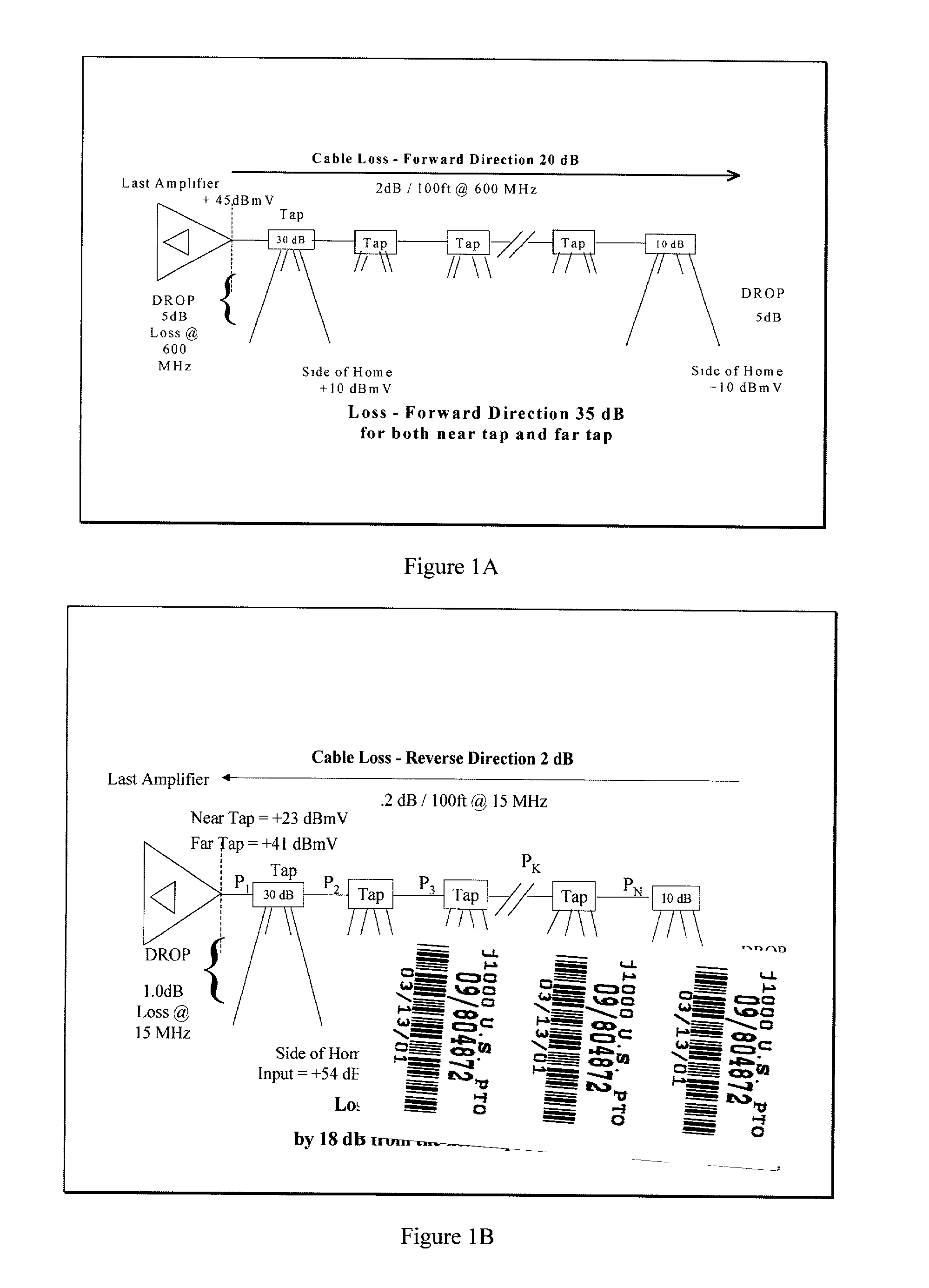
The reason is that the loss plan for the forward direction of the cable plant (or high frequency portion of the cable plant) is not the same as that for the reverse direction or low frequency portion of the cable plant due to the fact that cable loss increases with higher frequency.
As one moves further away from the last two-way amplifier, loss in the forward direction is the result of a combination of distribution trunk losses as well as tap (directional coupler) losses.
One of the operational side effects of this is that RF signals exiting every subscriber premise network do not arrive at the first amplifier (or subsequent return amplifiers and by extrapolation, the cable system headend) at the same nominal level.
Besides the obvious effect that an amplifier might go into overload, it becomes difficult to calculate the Carrier-to-Noise Ratio (CNR) and predict the expected system transmission performance when:
The problem with this approach to organizing the return path of a cable system is that the cable system is now more susceptible to noise that enters through directional couplers furthest from the first return amplifier A second problem with this approach is that reducing the NIU transmitter signal strength substantially reduces the Carrier to Noise (C / N) of the return signal.
The Carrier to Noise ratio under this situation could be as low as 10 dB, which is inadequate for most two-way cable applications.
However, any rise in the noise power by 1-3 dB could result in highly errored traffic in the reverse signal path.
The problem the cable operators now face is how to attack the second, and larger source of ingress noise, the customer premise distribution system.
This fact has led to the following problem--most, if not all, of the noise introduced in the return path of today's two-way HFC network originates within the subscriber's premise cable system network.
Ingress within the subscriber premise can occur when subscribers build out their premise cable plant and do not use high quality, heavily shielded cable, do not use high quality splitters, do not terminate unused drops, and do not attach connectors properly, among other causes.
This approach has been, for the most part, rejected for reasons of cost and the belief that this will not solve the noise problem because cable subscribers will, over time, modify and build out these networks and the cable operator will be left with the same problem after incurring the cost of replacing the premise network.
Again, this solution is expensive and is still subject to noise and interfering signals being superimposed on the "connector cables" between the wall and the NIU.
The problem with all of these solutions is that they really do not solve the problem of noise egressing from the premise network into the outside cable plant.
These approaches only mask or delay when the problem begins to affect the outside cable network and its performance.
The subscriber's premise cable system wiring will be subjected to high levels of RF noise from AC motors, fluorescent lights, 60 cycle noise, and other subscriber based noise and interference sources.
The subscriber's premise distribution system is unlikely to ever be replaced, and even if it were replaced, would still be a source of noise into the outside cable system.

Method used


Image

  • Method and apparatus for reducing the flow of RF noise from subscriber's premise cable systems into the reverse transmission path of two-way cable networks
  • Method and apparatus for reducing the flow of RF noise from subscriber's premise cable systems into the reverse transmission path of two-way cable networks
  • Method and apparatus for reducing the flow of RF noise from subscriber's premise cable systems into the reverse transmission path of two-way cable networks

Examples


Embodiment Construction

[0035] The first embodiment, shown in FIG. 2, consists of two devices 10 and 40, one active (10) and one passive(40). The system is designed to boost signals transmitted on the reverse spectrum placed on the subscriber's premise network 35 before it is corrupted by noise 36 which enters the premise network 35. The active unit 10 consists of a set of diplex filters, 20 and 25, that separate the forward (50-750 / 850 MHz) path, 21, and reverse (5-30 / 36 / 42 MHz) RF path, 22, and a booster amplifier 30 which is placed in the reverse bandwidth path 22. The active unit 10 is placed immediately next to an NIU 15 such as a digital set top box or a cable data modem. Signals from the outside cable plant 60 in the 50-750 / 850 MHz spectrum enter the passive unit 40 and pass through the high pass portion of diplex filters 50 and 55 via path 51 and are directed to the premise cable network 35 where they are broadcast to all attached devices. These high band signals then enter the active device 10, pa...


PUM


Abstract

What is disclosed is a method and means for reducing the RF noise induced within cable networks within residences or businesses from entering hybrid fiber optic coax networks in the reverse (upstream) direction. The active unit consists of a set of diplex filters connected end to end which segregates the RF traffic into a forward (nominally 50-750 / 850 MHz) and a reverse (nominally 5-30 / 36 / 42 MHz) direction but with an amplifier placed in the low band path. In the simplest embodiment, the active unit is attached directly to an Network Interface Unit (NIU). Signals from the NIU are amplified as they pass through the active unit and are then transmitted through the premise distribution network. The active unit is designed to boost the signals before they are mixed with noise present within the subscriber's premise network. At a second point in the network, typically at the side of the home where the residential premise network connects to the outside cable plant, the network passes through a second passive unit. The passive unit consists of a pair of diplex filters but on the low band path of the diplex filter pair there is an attenuator which attenuates signals in the reverse direction by nominally 15-35 dB, depending upon the value chosen for the attenuator. The attenuator may be either fixed, variable, or a combination of both and will be chosen by the design rules described below. The amplified RF signal and all noise that has entered the premise network cable system in the reverse path are attenuated and then passed through to the outside cable plant.

Description

BACKGROUND OF INVENTION[0001] This invention relates to the field of telecommunications in general and the reduction of RF noise induced within cable networks within residences or businesses from entering hybrid fiber optic coax networks in the reverse (upstream) direction.[0002] Currently, traditional coaxial cable networks are being upgraded from one way broadcast systems to two-way communications networks. The upgrade process consists of nominally extending fiber optics into the cable plant to create nodes or sub-networks of approximately 400-500 homes (or subscribers) passed per node, enabling the upstream or return communications path by installing reverse amplifiers into the cable plant and a return laser in the fiber node, and tightening the cable plant to preclude or minimize stray RF signals from interfering with the return RF signals. In most US based two-way cable systems, the RF bandwidth from 5-30 / 36 / 42 MHz is allocated as the "return path" of the RF cable spectrum supp...

Claims


Application Information

Patent Timeline
IPC IPC(8): H04N7/173H04N21/61
CPCH04N7/17309H04N21/6168H04N21/6118
Inventor MCNAMARA, ROBERT
Owner MCNAMARA ROBERT
Why Eureka
Try Eureka