Accurate target detection system

a target detection and accurate technology, applied in the field of target detection systems, can solve the problems of increasing the probability that a target will go undetected, reducing the probability, and inefficient use of a single threshold range for all detectors in the array

Inactive Publication Date: 2002-07-04
RAYTHEON CO
View PDF0 Cites 68 Cited by
  • Summary
  • Abstract
  • Description
  • Claims
  • Application Information

AI Technical Summary

Problems solved by technology

However, decreasing the probability of false detection may increase the likelihood that a target will go undetected.
Use of a single threshold range for all detectors in the array is inefficient, as the performance capabilities of individual detectors are often not maximized.
In existing systems, if the background estimation circuit remains enabled, target information may corrupt the background estimates.
The corrupted values may greatly reduce the target detection capability of the system.
Accordingly, many existing target detection systems fail to account for variations in background that often occur during system operation.
As a result, the ability of such target detection systems to accurately detect targets is compromised.

Method used


Image

  • Accurate target detection system
  • Accurate target detection system
  • Accurate target detection system

Examples


Embodiment Construction

[0025] While the present invention is described herein with reference to illustrative embodiments for particular applications, it should be understood that the invention is not limited thereto. Those having ordinary skill in the art and access to the teachings provided herein will recognize additional modifications, applications, and embodiments within the scope thereof and additional fields in which the present invention would be of significant utility.

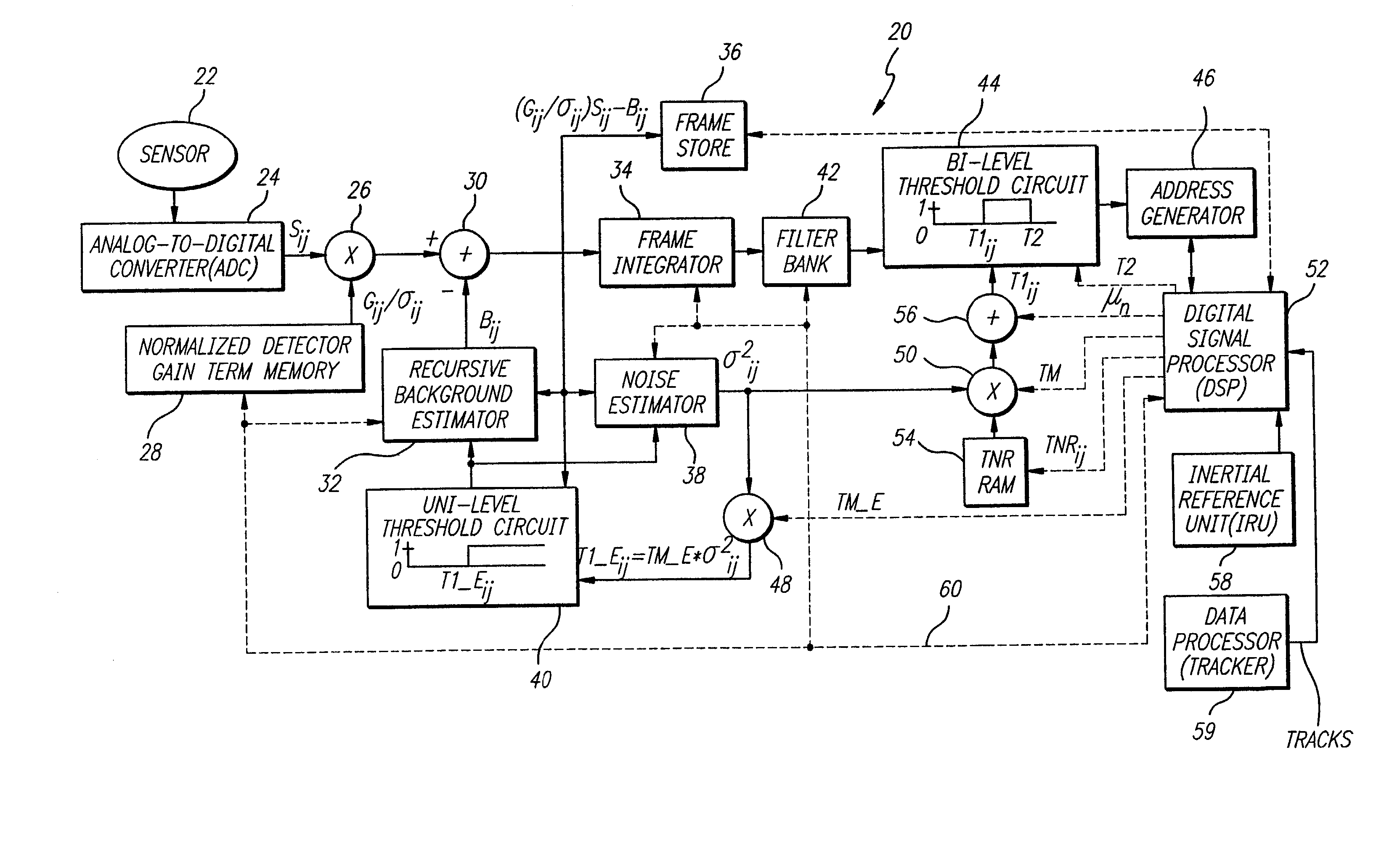
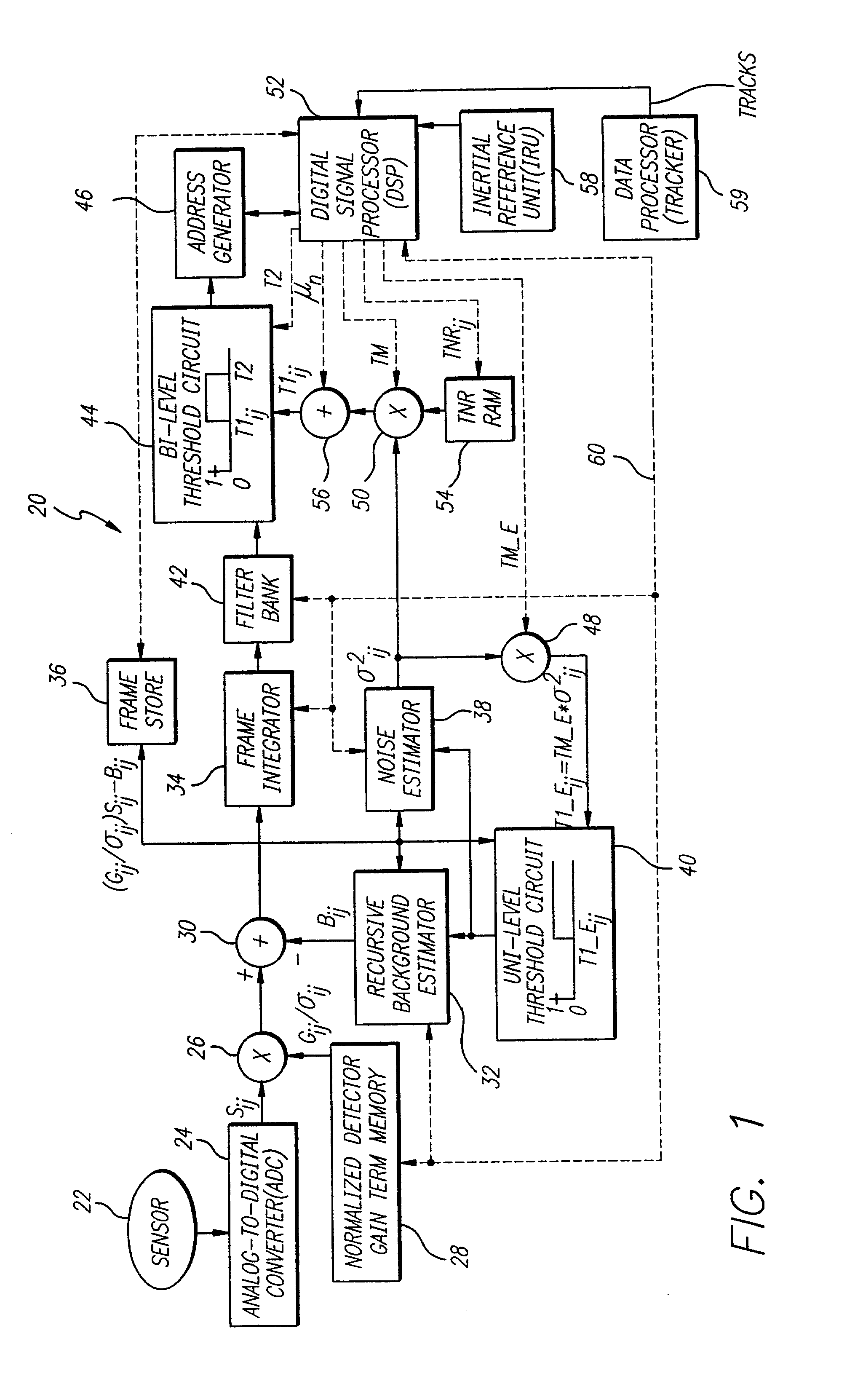
[0026] FIG. 1 is a diagram of a target detection system 20 constructed in accordance with the teachings of the present invention. The target detection system 20 includes a sensor 22, the output of which is connected to a analog-to-digital converter (ADC) 24. An output of the ADC 24 is connected to a first input of a first multiplier 26. A second input of the first multiplier 26 is connected to an output of a normalized detector gain term memory 28. An output of the first multiplier 26 is connected to a positive terminal of a subtract...


PUM


Abstract

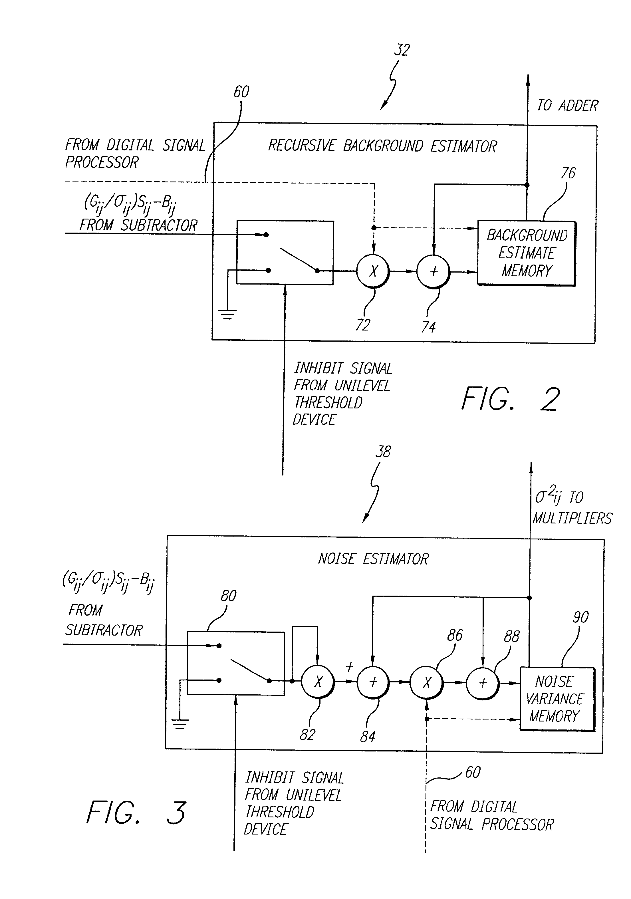
An accurate target detection system. The system includes a sensor (22) that receives electromagnetic signals and provides electrical signals in response thereto. A non-uniformity correction circuit (28, 38, 52) corrects non-uniformities in the sensor (22) based on the electrical signals and provides calibrated electrical signals in response thereto. A third circuit (30, 32, 34, 38, 42, 44, 52) determines if a target signal is present within the calibrated electrical signals and provides a target detection signal in response thereto. A fourth circuit (38, 40, 48) selectively activates or deactivates the non-uniformity correction circuit (28, 38, 52) based on the target detection signal. In a specific embodiment, the sensor (22) is an array of electromagnetic energy detectors (22), each detector providing an electrical detector output signal The non-uniformity correction circuit (28, 38, and 52) includes circuit for compensating for gain, background, and noise non-uniformities (28, 38, and 52) in the electromagnetic energy detectors. The non-uniformity correction circuit (28, 38, and 52) includes a detector gain term memory (28) for storing detector gain compensation values. The detector gain compensation values are normalized by noise estimates unique to each of the detectors. The third circuit (30, 32, 34, 38, 42, 44, and 52) includes a signal enhancement circuit for reducing noise (34, 42) in the calibrated electrical signals. The third circuit (30, 32, 34, 38, 42, 44, and 52) includes a noise estimation circuit (32, 38) that estimates noise in each of the detector output signals and provides noise estimates in response thereto. The noise estimation circuit (32, 38) further includes a noise estimator circuit (38) and a recursive background estimator (32). The third circuit (30, 32, 34, 38, 42, 44, 52) further includes a subtractor (30) for subtracting background from the calibrated electrical signals and providing background subtracted signals in response thereto. The signal enhancement circuit (34, 42) includes a frame integrator circuit for adding frames of image data (34), each frame containing data corresponding to the background subtracted signals and providing summed frames in response thereto. The third circuit (30, 32, 34, 38, 42, 44, 52) includes a first threshold circuit (44) for comparing the filtered signal to a first threshold and a second threshold and providing a threshold exceedance signal if the filtered signal is between the first threshold and the second threshold.

Description

[0001] 1. Field of Invention[0002] This invention relates to target detection systems. Specifically, the present invention relates to systems employing electro-optical sensors to detect targets using constant false alarm rate detection processes[0003] 2. Description of the Related Art[0004] Target detection systems are used in a variety of demanding applications including radar air traffic control systems, missile target tracking systems, and electro-optical target detection systems employed on aircraft and ground-based military vehicles. Such applications often require accurate target detection systems that produce minimal false detections.[0005] A target detection system typically includes an electromagnetic energy sensor that receives electromagnetic signals such as optical signals and outputs electronic signals in response thereto. A processing circuit analyzes the electronic output signals to determine if a target is present in the field of view of the sensor.[0006] The sensor ...

Claims


Application Information

Patent Timeline
Patent Type & Authority Applications(United States)
IPC IPC(8): G01S3/786G01S13/72
CPCG01S3/7864G01S13/723H04N5/33H04N5/3651H04N25/671
Inventor BAKER, TODD L.CABER, TIMOTHY E.DANG, HIEN T.LO, THOMAS K.WALD, SHELDON S.
Owner RAYTHEON CO
Why Eureka
Try Eureka