

Micro-motor and apparatus using the same motor
a micro-motor and motor technology, applied in the field of micro-motors, can solve the problems of unstable r.p.m. of the motor, failure to keep the shaft 358 stably,
- Summary
- Abstract
- Description
- Claims
- Application Information
AI Technical Summary
Benefits of technology
Problems solved by technology
Method used
Image

Examples
first exemplary embodiment
[0030] First Exemplary Embodiment
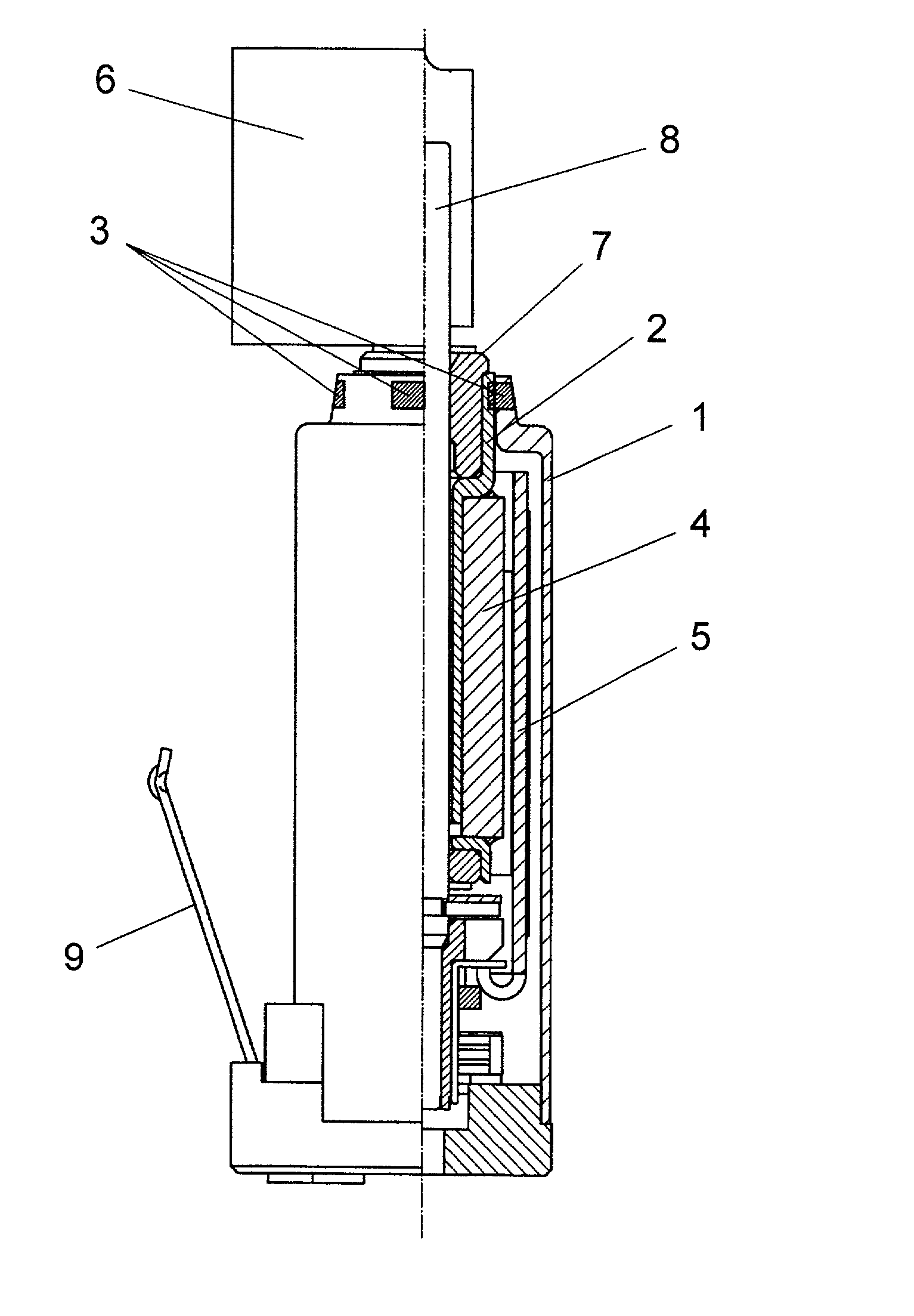
[0031] FIG. 1 shows a structure of a motor in accordance with the first exemplary embodiment of the present invention.
[0032] The motor in accordance with the first embodiment includes slim and cylindrical frame 1 made of ferromagnetic material. Within socket frame 1, plug pipe 2 is fixed concentrically with frame 1. On the inner wall of a first side of pipe 2, sintered bearing 7 is press-fitted. On the outer wall of a second side of pipe 2, an inner wall of cylindrical magnet 4 is fixed. Further, cylindrical coil 5 surrounds magnet 4, in other words, coil 5 faces the outer wall of magnet 4 via an annular space.
[0033] Coil 5 is connected to a commutator, and motor terminal 9 is connected to a brush. An outer power source (not shown) applies a voltage across terminal 9, thereby powering coil 5 via the sliding contact between the brush and the commutator. Magnet 4 functions as a stator that forms magnetic field, and coil 5 functions as a rotor that spin...
second exemplary embodiment
[0036] Second Exemplary Embodiment
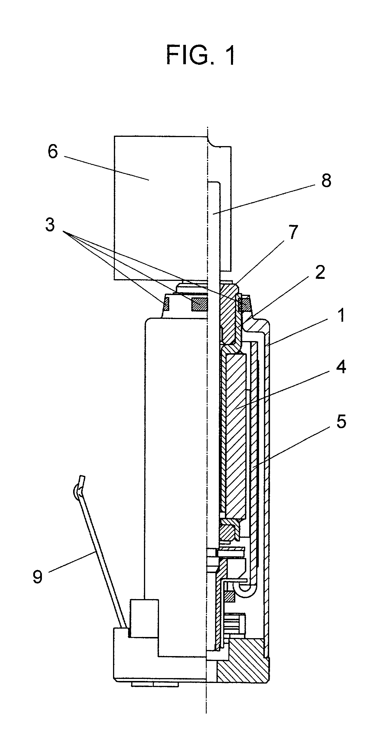
[0037] FIG. 2 shows a structure of a motor in accordance with the second exemplary embodiment of the present invention. The motor in accordance with the second embodiment differs from the motor of the first embodiment in a method of welding at the fitted section between frame 1 and pipe 2. In other words, laser welding 3a is provided to the fitted section between frame 1 and pipe 2 in this second embodiment, and otherwise the structure in accordance with the second embodiment remains the same as that of the first one. In the second embodiment, if large vibrator 6 is attached to shaft 8, no problem occurs at a drop shock, and the motor thus can produce great vibrations as same as the first embodiment.
[0038] The fit-in margin (the difference between the inner diameter of socket frame 1 and the outer diameter of plug pipe 2, where the inner diameter is equal to or less than the outer diameter) is specified ranging from 0 .mu.m (included) to 20 .mu.m (n...
third exemplary embodiment
[0039] Third Exemplary Embodiment
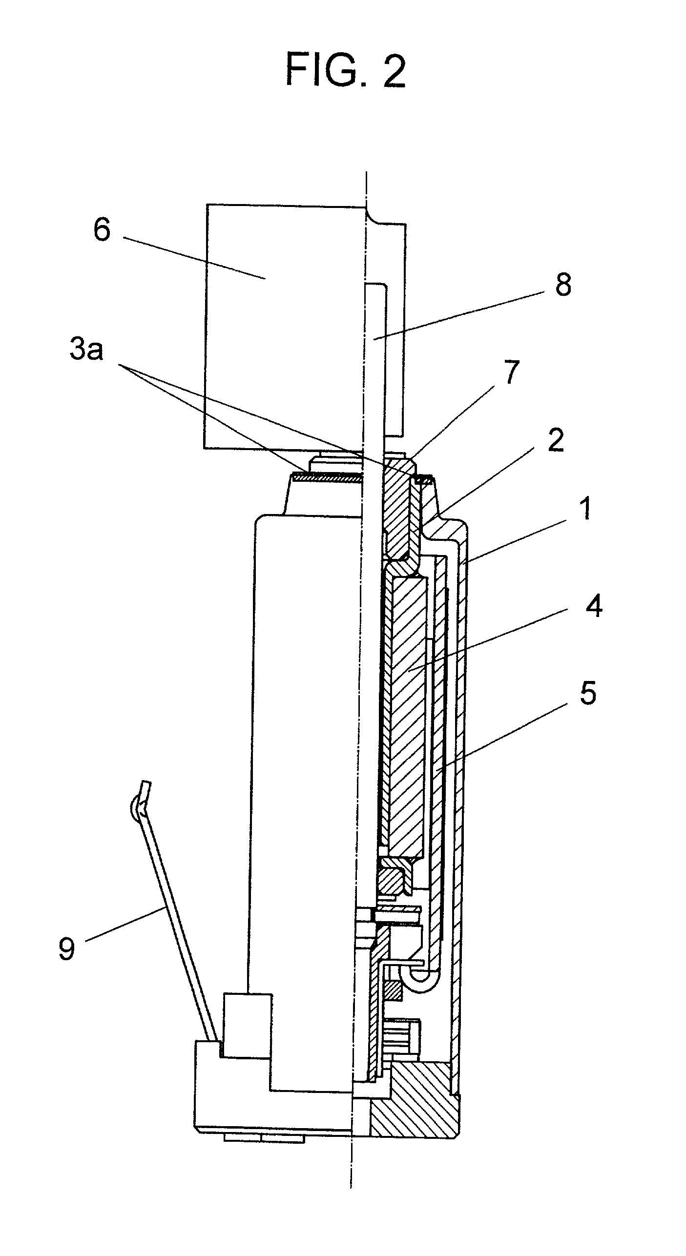
[0040] FIG. 3 shows a structure of a motor in accordance with the third exemplary embodiment of the present invention. The motor in accordance with the third embodiment includes slim and cylindrical frame 31 made of ferromagnetic material. Within frame 31, sintered bearing 37 is concentrically fixed to frame 31. On the outer wall of bearing 37, the inner wall of cylindrical magnet 34 is fixed. Further, cylindrical coil 35 surrounds magnet 34, in other words, coil 35 faces the outer wall of magnet 34 via an annular space.
[0041] Coil 35 is connected to a commutator, and motor terminal 39 is connected to a brush. An outer power source (not shown) applies a voltage across terminal 39, thereby powering coil 35 via the sliding contact between the brush and the commutator. Magnet 34 functions as a stator that forms magnetic field, and coil 35 functions as a rotor that spins outside magnet 34. Rotor coil 35 is coupled to shaft 38, and one end of shaft 38 is ...
PUM
 Abstract
Description
Claims
Application Information