Sensor fusion apparatus and method for optical and magnetic motion capture systems

a technology of fusion apparatus, which is applied in the field of sensor fusion apparatus and method for optical and magnetic motion capture system, can solve the problems of inconvenient motion execution, difficult to smoothly capture athletic game motions, and become a tedious and time-consuming work

Inactive Publication Date: 2002-07-25
ELECTRONICS & TELECOMM RES INST
View PDF5 Cites 40 Cited by
  • Summary
  • Abstract
  • Description
  • Claims
  • Application Information

AI Technical Summary

Problems solved by technology

While, the magnetic equipment has a shortcoming as a possibility that metallic material positioned at a capture area may cause noise at final data, it may be inconvenient to execute a motion owing to the number of cables connected to the performer, and most athletic game motions may be difficult to be smoothly captured due to a low sampling rate.
In other words, there may be several kinds of problems that one marker or more is hidden during the capture through a use of the optical equipment, marker swapping can occur, and an error provided due to vanished data or mixed-noise data, and error reflection, etc., is caused.
Therefore, motion data recorded after a motion capture session should be definitely post-processed or tracked, which may become a very tedious and time-consuming work according to an extent of a quality and a required fidelity of the captured data.
However, the conventional motion capture has selected and used a proper motion capture system according to a purpose of the work, and it has not ever been proposed a method for lessening a burden of the post processing work and gaining precise data by using two or more kinds of motion capture systems.
At this time, since the optical marker may be covered with an obstacle, information of the optical marker may become incomplete.

Method used


Image

  • Sensor fusion apparatus and method for optical and magnetic motion capture systems
  • Sensor fusion apparatus and method for optical and magnetic motion capture systems
  • Sensor fusion apparatus and method for optical and magnetic motion capture systems

Examples


Embodiment Construction

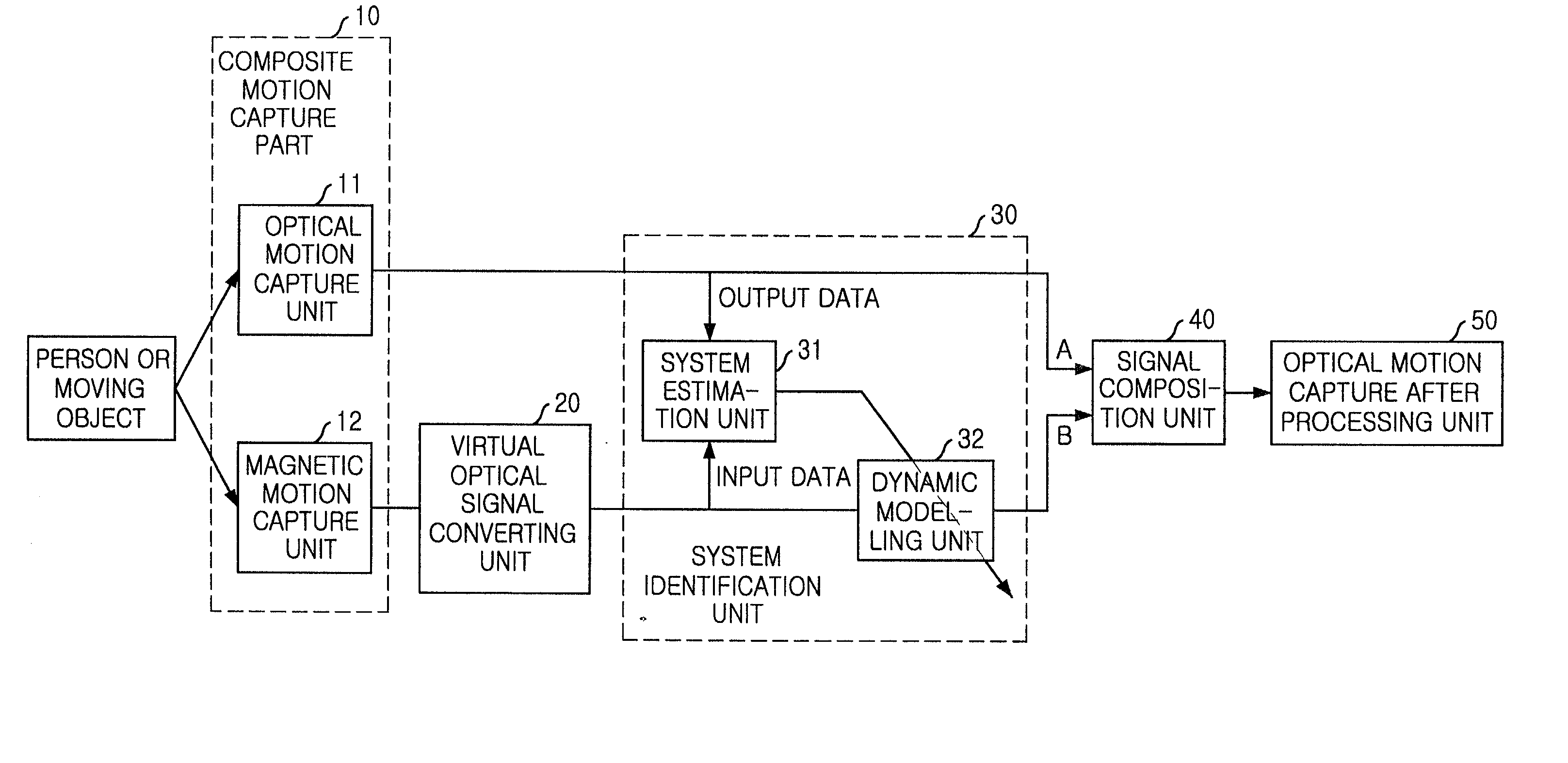
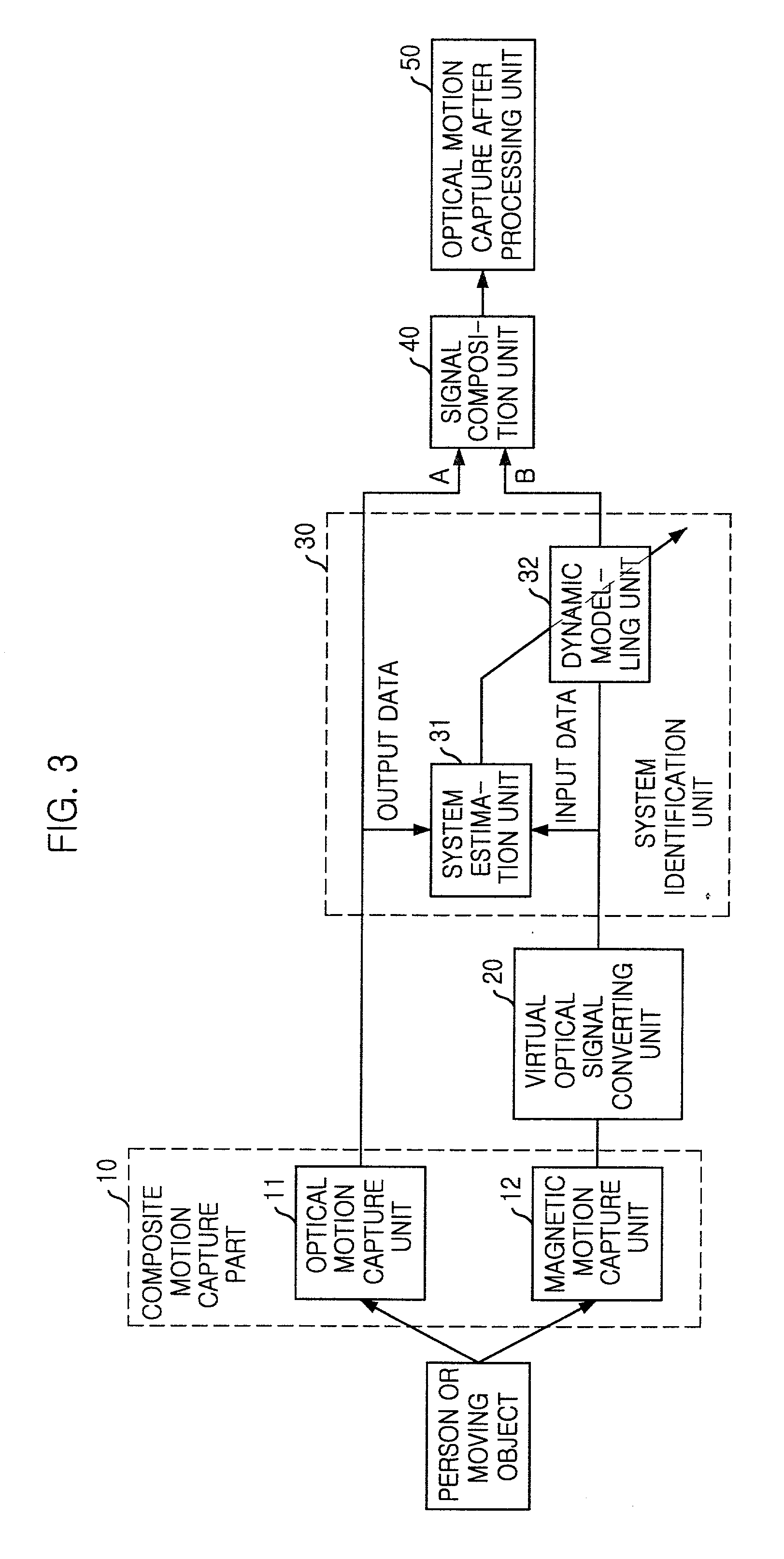
[0025] Hereinafter, preferred embodiments of the present invention will be described in detail with reference to the accompanying drawings.

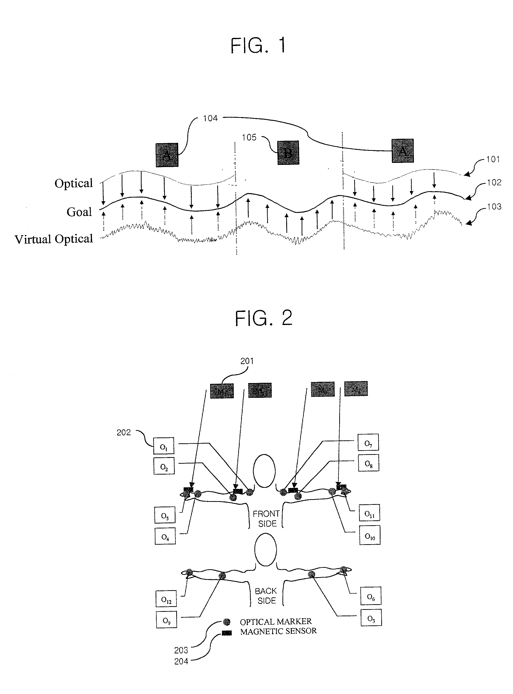
[0026] FIG. 1 is an explanatory diagram of a marker signal for a sensor fusion in one embodiment of the present invention.

[0027] In FIG. 1, a reference number 101 represents an optical marker signal for indicating position data of an optical marker captured through an optical motion capture system.

[0028] A reference number 102 is a goal signal to be gained through a sensor fusion.

[0029] A reference number 103 is a virtual optical marker signal as a result obtained by converting position and bearing data of a magnetic sensor captured through a magnetic motion capture system into a corresponding optical marker signal.

[0030] A reference number 104 indicates a normal operating section of an optical system.

[0031] A reference number 105 is an abnormal operating section of the optical system where an optical marker signal does not exist by a hiding of a...


PUM


Abstract

In a sensor fusion apparatus and method for optical and magnetic motion capture systems and a record medium capable of being read through a computer having a writing of a program to realize the inventive method, in which a shortcoming of respective systems can be overcome and merits can be led by simultaneously using the optical motion capture system (OMCS) and the magnetic motion capture system (MMCS) to obtain motion capture data more precisely, the method includes a first step of obtaining an optical marker signal and a magnetic sensor signal for the motion capture object; a second step of converting the magnetic sensor signal into a corresponding optical marker signal, and acquiring a virtual optical marker signal; a third step of modeling a relation between the virtual optical marker signal and the optical marker signal to a dynamic model through a system identification; and a fourth step of using the optical marker signal as it is, when the optical marker signal is normal, and using a signal gained by inputting the virtual optical signal into the dynamic model, as a usage for a correction of the optical marker signal, by using the dynamic model when the optical marker signals are discontinuous, according to a normal or abnormal state of the optical marker signal.

Description

[0001] The present invention relates to a sensor fusion apparatus and method in a motion capture system for an animation of a person or moving object provided on a three-dimensional virtual space, and a record medium capable of being read through a computer having a writing of a program to realize the inventive method; and more particularly, to a sensor fusion apparatus and method for a motion capture system, in which a shortcoming of respective systems can be overcome and merits can be led by simultaneously using an optical motion capture system (OMCS) and a magnetic motion capture system (MMCS) in order to obtain motion capture data more precisely.PRIOR ART OF THE INVENTION[0002] A motion capture means a serial procedure of acquiring a motion of an object and mapping it to a virtual object generated by a computer.[0003] The motion capture is mainly used in capturing the motion of people and producing a composed virtual performer. That is, a specially manufactured marker or sensors...

Claims


Application Information

Patent Timeline
Patent Type & Authority Applications(United States)
IPC IPC(8): G06T7/20G06T13/00G06T15/70
CPCG06F3/011G06K9/00335G06K2009/3225G06T7/0071G06T7/2033G06T7/579G06T7/246G06V40/20G06V10/245G06T7/20
Inventor JEONG, IL-KWONKIM, DO-HYUNGLEE, IN-HOOH, WEON-GEUN
Owner ELECTRONICS & TELECOMM RES INST
Why Eureka
Try Eureka