Hydraulic control device, system and method for controlling actuator device

a technology of hydraulic control device and actuator device, which is applied in the direction of electric control, machines/engines, mechanical equipment, etc., can solve the problems of system lifting, and inability to completely handle the requirement for reducing exhaust gases

Inactive Publication Date: 2002-08-29
DENSO CORP
View PDF3 Cites 14 Cited by
  • Summary
  • Abstract
  • Description
  • Claims
  • Application Information

AI Technical Summary

Problems solved by technology

The rise of the back pressure causes the needle to drop, thereby interrupting the injection of fuel.
Recently, however, it is examined to carry out the depressurization control through the hydraulic control valve without providing the special depressurization valve.
Variations of the performances of actuator devices are generated among each other due to the unevenness among the designs or qualities of the manufactured actuator devices.
Even when, therefore, energizing the actuators of the actuator devices at the same timing, the timings of fuel injections of the actuator devices or the quantities of fuel thereof, which are injected therefrom, are relatively different from each other, so that it is impossible to completely handle a requirement for decreasing exhaust gases in recent years and other similar requirements.
However, the above conventional fuel injection system requires the great energy to lift from the low pressure port the valve member subjected to the fuel pressure in the high pressure port.
The requirement of the great energy and the application of the fuel pressure in the lifting direction make it extremely difficult to control stably the valve member so as to keep it at a half-lift position between the low pressure port and the high pressure port.
In the present circumstances, therefore, it is hard to carry out the half-lift control of the valve member in the conventional fuel injection system to which the hydraulic control valve with the above described configuration is applied.
In addition, in cases where the operating characteristics of actuators themselves determine the operating conditions of some actuator devices in which the actuators are installed, respectively, the operating conditions of some actuator devices do not very vary among each other.
For example, in a part of injectors, the pressing force of the actuator required for moving the valve member or the needle away from the position at which the valve member or the needle is seated is relatively insufficient, causing the seat of the valve member or the needle to be instable.
However, in some actuator devices, such as engines performing a greatly number of fuel injections, whose actuators frequently operate, delivering excessively great quantity of energy to the actuators causes a heavy energy loss.
Moreover, delivering excessively great quantity of energy to the actuators also causes heat generation in some actuator devices, and causes excessive wear of each component of some actuator devices to be accelerated.
These problems bring about variations of the injection characteristics of the injectors with time, so that even when adopting the techniques described in the U.S. Pat. No. 5,634,448 to the actuator device, it is not necessarily to perform fuel injection with a high degree of accuracy.
The supplied energy, however, is smaller than energy which the actuator requires to move the valve member so as to close the high pressure port so that it is impossible to close the high pressure port by the valve member.

Method used


Image

  • Hydraulic control device, system and method for controlling actuator device
  • Hydraulic control device, system and method for controlling actuator device
  • Hydraulic control device, system and method for controlling actuator device

Examples


first embodiment

[0044] (First embodiment)

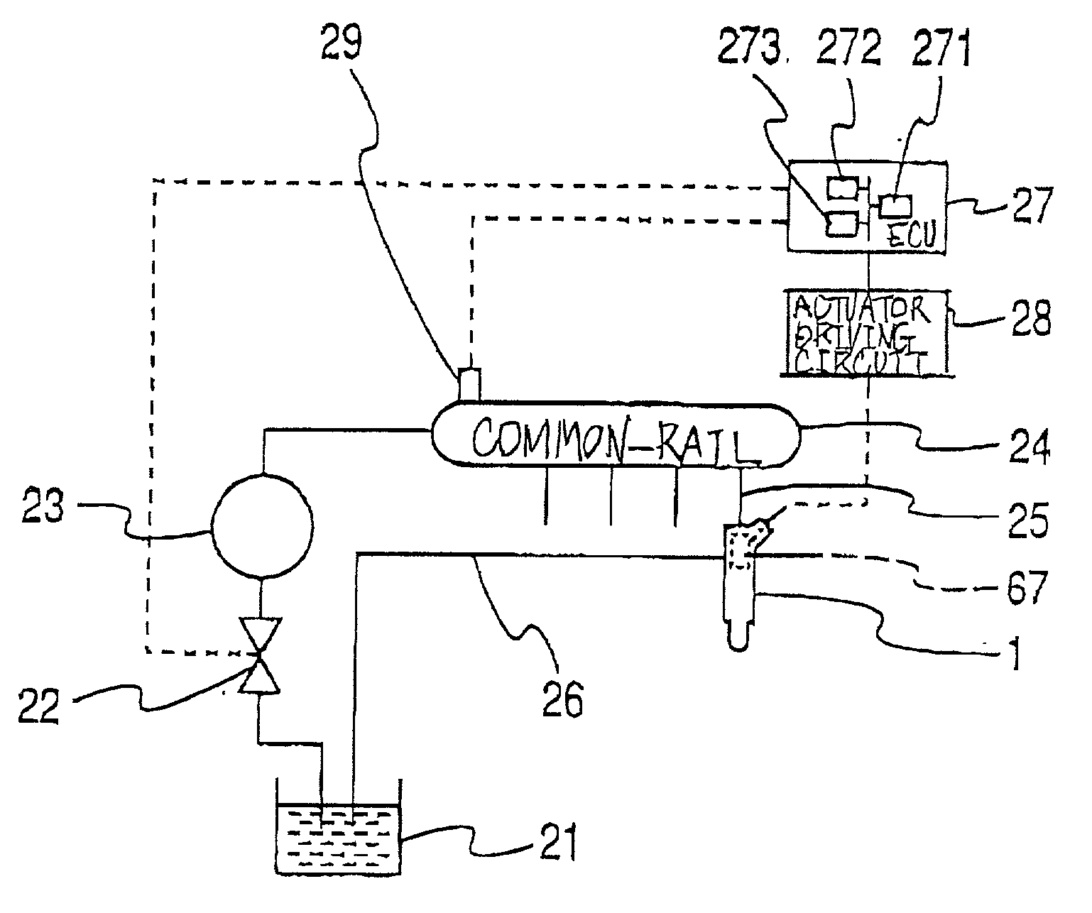
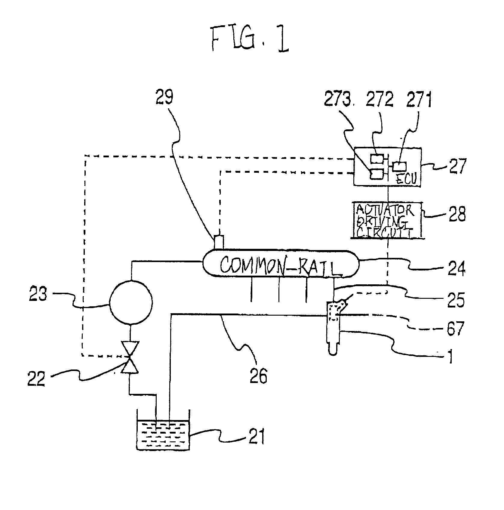
[0045] FIG. 1 shows a configuration of a common-rail fuel injection system to which a first embodiment of the present invention is applied.

[0046] The common-rail fuel injection system comprises injectors (fuel injection valves) 1 for respective cylinders of the common-rail fuel injection system. A number of injectors correspond to that of cylinders of the common-rail fuel injection system. Incidentally, in FIG. 1, one injector 1 is only shown.

[0047] The injector 1 is communicated through a delivery line 25 with a common-rail 24, which is common among the cylinders. The injector 1 is subjected to the fuel delivered from the common-rail 24 so as to inject fuel at an injection pressure into a combustion chamber of the corresponding cylinder, injection pressure which is substantially equal to a fuel pressure in the common-rail 24.

[0048] Fuel in a fuel tank 21 is delivered by the pressure of a high-pressure pump 23 to a common-rail 24 so as to be accumulated ther...

second embodiment

[0128] (Second embodiment)

[0129] In this second embodiment, the configurations of the fuel injection system and the injector 1A are substantially the same as those of the fuel injection system and the injector 1 of the first embodiment, and therefore, the elements of the fuel injection system and the injector 1A of the second embodiment, which are the same as those of the fuel injection system and the injector 1 of the first embodiment, are given the same characters in FIGS. 1.about.3.

[0130] According to the second embodiment, on the ROM 273A, reference voltages V0 of corresponding injectors 1A, reference actuator temperatures T0 thereof, a reference common-rail pressure P0 and a reference lift amount L0 are previously stored as data in addition to the program.

[0131] Furthermore, according to the second embodiment, the CPU 271A of the ECU 27A executes a control program, which is different from that of the first embodiment, so as to control the piezoelectric actuator 67.

[0132] FIG. 5...


PUM


Abstract

A supplying unit supplies energy to an actuator so that the supplied energy is kept therein, making displacement the actuator. An interrupting unit interrupts the supply of energy to cause the actuator to discharge the kept energy, making displacement the actuator. A converting unit is adapted to convert the displacement of the actuator corresponding to the kept energy into hydraulic pressure applied to the valve member, moving the valve member to open the low pressure port and close the high pressure port. The convert unit converts the displacement of the actuator corresponding to the discharged energy into hydraulic pressure applied to the valve member, moving the valve member to open the high pressure port and close the low pressure port. Energy which the actuator requires to move the valve member so as to close the high pressure port is larger than energy which the actuator requires to move the valve member so as to open the low pressure port.

Description

[0001] 1. Field of the Invention[0002] The present invention relates to an actuator device, such as a hydraulic control device, in which an actuator is installed, a control system and a method for the actuator device.[0003] More particularly, the present invention relates to an actuator device, such as a hydraulic device, applied to, for example, an internal combustion engine, such as a diesel engine, a control system and a method for the actuator device.[0004] 2. Description of the Related Art[0005] Conventional actuators that energization can make operate include an actuator, such as a piezoelectric actuator, a magnetostrictive actuator, or the like, which deforms according to amount of energy based on the energization and kept by itself, thereby generating driving force, such as pressing force. Conventional actuator devices in each of which the above actuator is installed, such as, hydraulic control valves, fuel injectors and so on, are proposed.[0006] The actuator devices are ap...

Claims


Application Information

Patent Timeline
Patent Type & Authority Applications(United States)
IPC IPC(8): F02D41/00F02D41/24F02D41/34F02M47/02F02M47/04F02M61/16F02M63/00F02M63/02
CPCF02D41/008F02D41/2435F02D41/2467F02D2200/0602F02M47/027F02M47/046F02M51/0603F02M61/167F02M63/0026F02M63/0225F02M2200/21F02M2200/704F02M2200/8007
Inventor IGASHIRA, TOSHIHIKOHAYASHI, SATOSHI
Owner DENSO CORP
Why Eureka
Try Eureka