Method and system for hot wire welding

a technology of hot wire welding and method, applied in the direction of welding/cutting media/materials, welding apparatus, manufacturing tools, etc., can solve the problems of affecting the quality of hot wire welding, and raising the possibility of many errors in the prior art system

Inactive Publication Date: 2002-08-29
LIBURDI ENG
View PDF0 Cites 38 Cited by
  • Summary
  • Abstract
  • Description
  • Claims
  • Application Information

AI Technical Summary

Problems solved by technology

This prior art system does not provide a coordinated control of components with respect to other components.
This operation raises the possibility of introducing many errors.
For example, an excessively high hot wire voltage results in the burning back or premature melting of the wire within the wire feed conduit or nozzle, which causes damage to the feeding system.
On the other hand, if there is insufficient hot wire voltage applied for a certain wire feed speed the wire will not adequately melt into the weld puddle and in some cases will shoot through the welding arc.
Another prior art problem is magnetic interference or "Arc Blow" caused by the AC voltage or high DC voltage applied to the filler wire by the constant voltage power source 14.
Magnetic interference causes the ma...

Method used


Image

  • Method and system for hot wire welding
  • Method and system for hot wire welding
  • Method and system for hot wire welding

Examples


Embodiment Construction

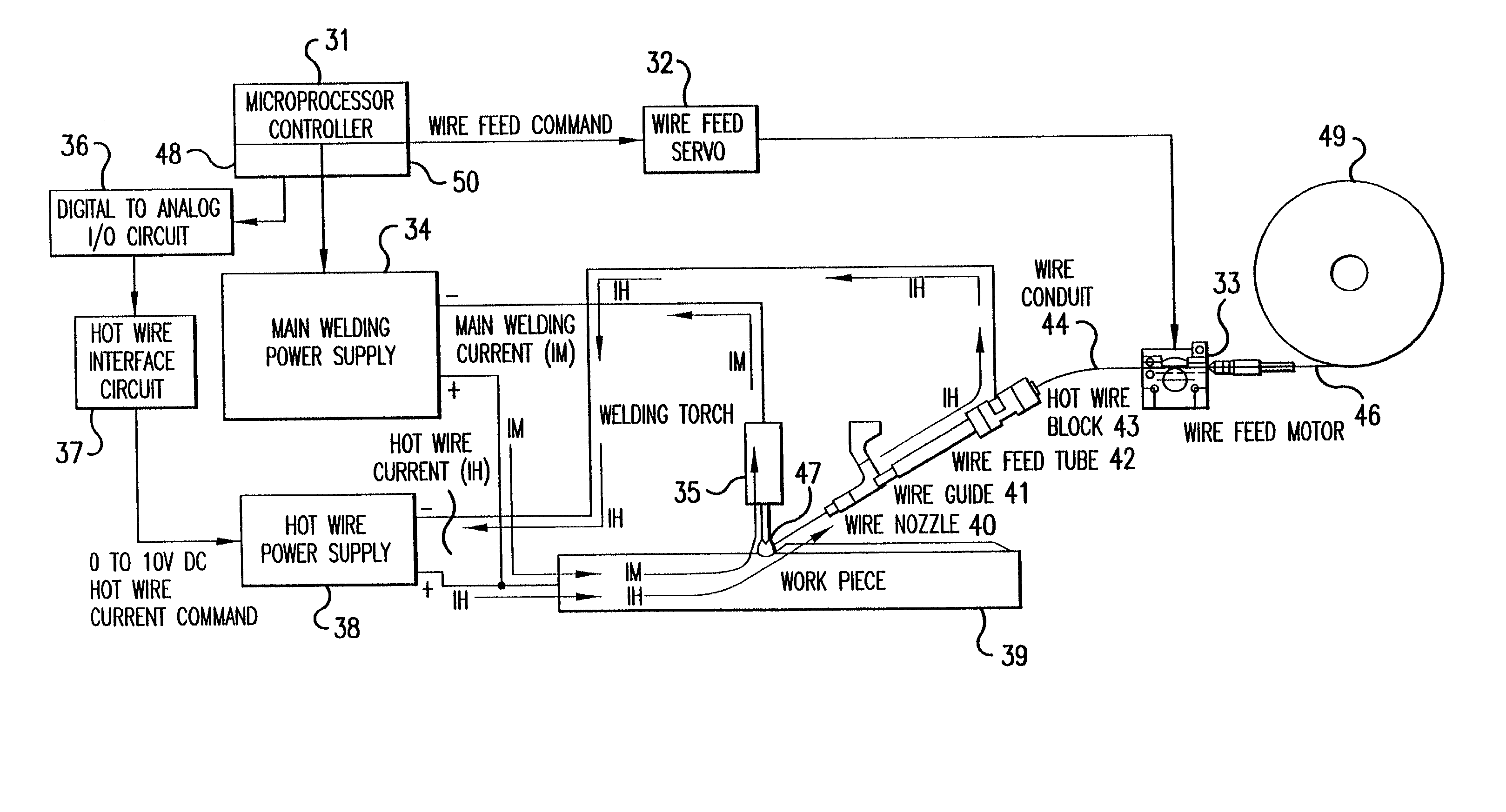
[0027] FIG. 3 is a block diagram of an embodiment of the present invention which provides simplified and easily overridden hot wire control. With reference to FIG. 3, a microprocessor controller 31 controls all aspects of the welding process. A wire feed servo 32 that is directed by the microprocessor controller 31 to maintain a desired filler wire speed. A wire feed motor 33 feeds the filler wire 46 into a welding puddle 47. This system also contains a main welding power supply 34 for supplying a main welding current to a torch 35 which preferable includes a non-melting tungsten electrode. A digital to analog output circuit 36 converts the digital control output of the microprocessor 31 to an analog signal. A hot wire power supply interface circuit 37 (shown in detail in FIG. 4) further amplifies the hot wire control signal and isolates it for protection from outside noise. This is a 0 to 10 VDC control signal that is then routed to a hot wire power supply 38, which in turn conduct...


PUM

PropertyMeasurementUnit
Poweraaaaaaaaaa
Flow rateaaaaaaaaaa
Speedaaaaaaaaaa

Abstract

A hot wire welding method and system includes a welding torch with a non-melting electrode, a melting metal filler wire fed into the weld puddle created by the welding arc, a microprocessor controller for controlling the current of the main welding arc, filler wire feed speed, and hot wire current control for the heating of the hot wire. The method and system also includes a main welding power supply for supplying the main welding arc and a secondary DC supply for supplying the hot wire current. The hot wire current is automatically controlled by the microprocessor to supply the correct amount of hot wire current to the filler wire with changes in wire feed speed.

Description

[0001] This is a continuation-in-part of U.S. application Ser. No. 09 / 793,547, filed Feb. 27, 2001 which in turn is a continuation of U.S. application Ser. No. 09 / 790,713, filed Feb. 23, 2001, which are hereby incorporated by reference.[0002] 1. Field of the Invention[0003] The present invention relates to hot wire welding. More specifically, the invention relates to a method and system for hot wire welding wherein control of the hot wire supply current is in direct relationship to the speed of the feed wire.[0004] 2. Description of the Prior Art[0005] The basic theory of Hot Wire (vs. Cold Wire) is to preheat the filler wire by running an electric current through it. The term "Hot Wire" is used because it is electrically hot, as well as physically hot. This allows a much higher disposition rate than conventional Cold Wire. The difference between the Hot Wire and Cold Wire systems is not striking until high feed rates are used. Generally, this rate will be above 130 inches per minut...

Claims


Application Information

Patent Timeline
IPC IPC(8): B23K9/095B23K9/10B23K9/167
CPCB23K9/0953B23K9/1093B23K9/167
Inventor ARNDT, TONY LEEDIK, ROGER CARLKASKINEN, PELLERVO JOHANNES
Owner LIBURDI ENG
Why Eureka
Try Eureka