
Configurable bio-transport system simulator

a bio-transport system and simulator technology, applied in biological models, instruments, analogue processes for specific applications, etc., can solve the problems of inherently difficult to study, potentially life-threatening, and inconvenient use, and achieve the effect of being easily customizabl

Inactive Publication Date: 2002-08-29
KEANE JOHN A
View PDF0 Cites 88 Cited by
  • Summary
  • Abstract
  • Description
  • Claims
  • Application Information

AI Technical Summary

Benefits of technology

Enables detailed and accurate simulation of bio-transport dynamics without the risks and constraints of real systems, facilitating research and clinical applications by providing sophisticated data on fluid flow, chemical concentrations, and pressure gradients, and allowing for the examination of alternative strategies and mechanisms.

Problems solved by technology

Despite the desire to analyze bio-transport dynamics of mass transport systems within organisms, the dynamic nature of these systems makes them inherently difficult to study.
Some of these tools are non-invasive but imprecise, such as sphygmomanometer, while others are precise but invasive, and potentially life threatening, such as cardiac catheterization.
Animal testing, however, is under scrutiny.
There are a number of practical difficulties, owever, associated with a pure theoretical analysis of bio-transport dynamics that are not normally encountered outside living organisms.
Piecemeal solutions that arise from considering only part of a problem-, or a radical simplification of the problem to obtain an assumption-restricted solution, while useful within the stipulated range of applicability, do not meet current and future clinical / research needs for scope, detail, accuracy and architecture.
Although such a model provides useful information on the circulatory system in gross terms, no detailed information with regard to spatial dependence of the system is available.
In other words, this model can only provide data on bulk values for variables in the circulatory system and not for different components of the system where data tend to vary as suggested by Lighthill.

Method used


Image

  • Configurable bio-transport system simulator
  • Configurable bio-transport system simulator
  • Configurable bio-transport system simulator

Examples


Embodiment Construction

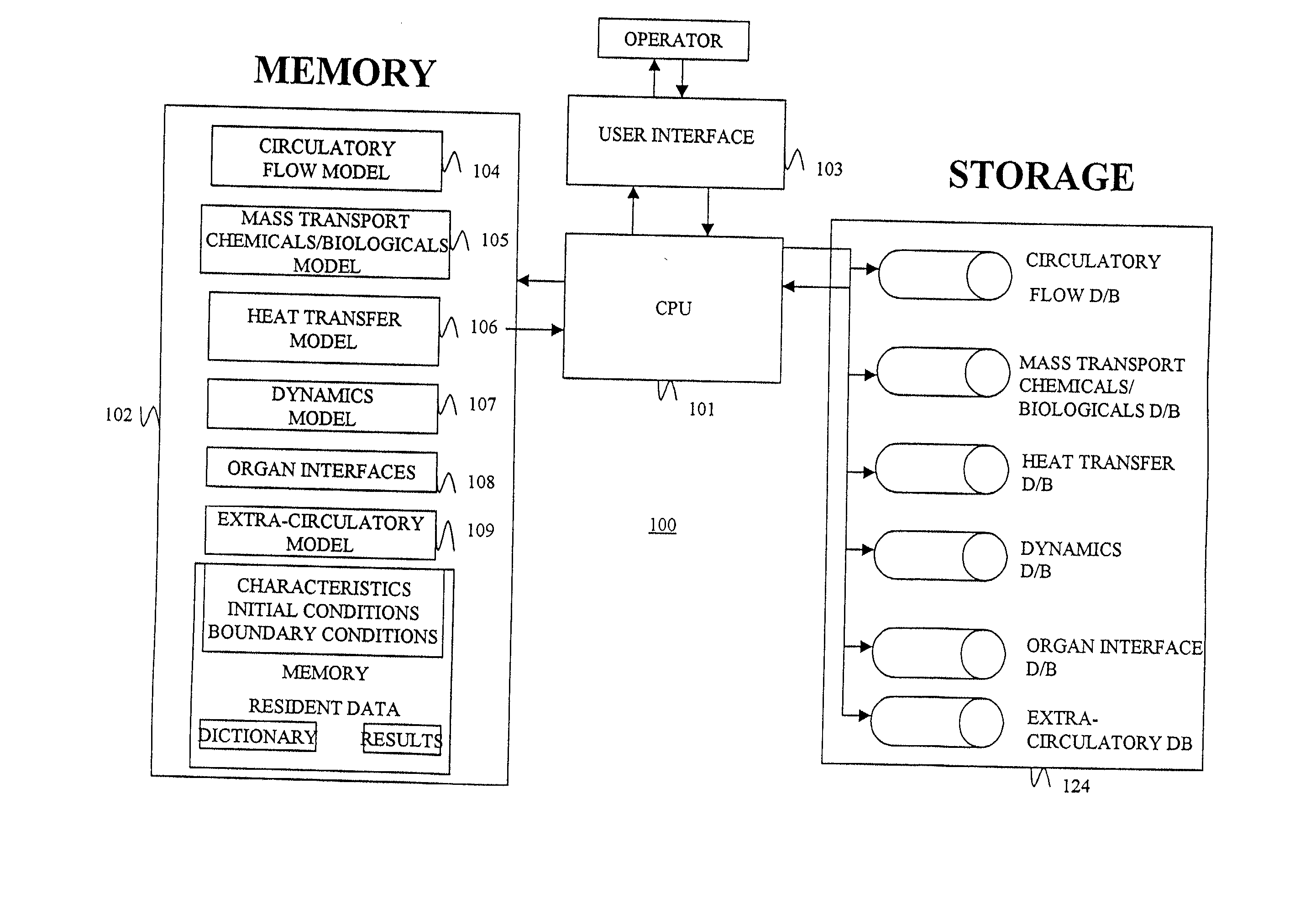
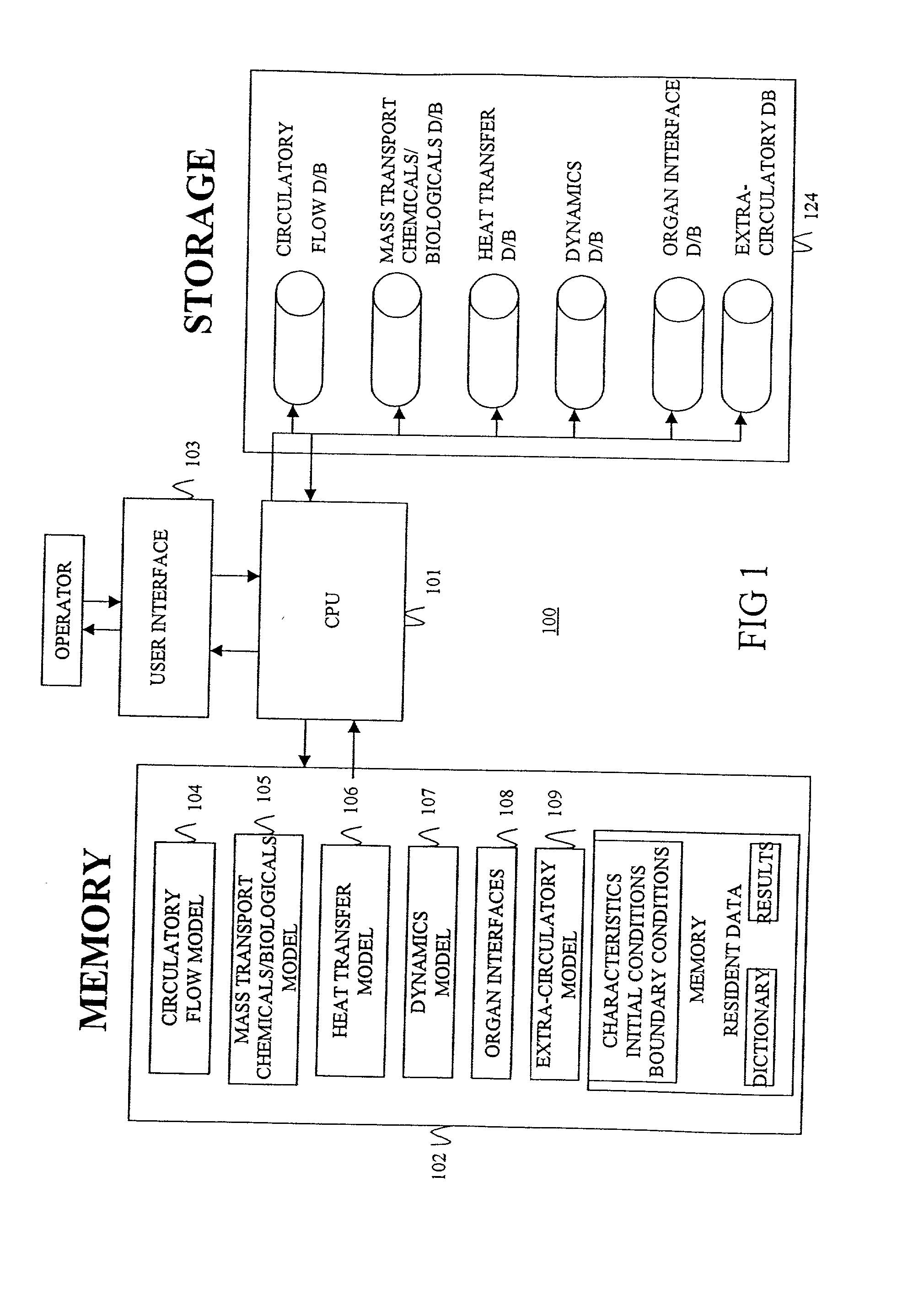
[0051] The present invention provides for a system and method for simulating bio-transport dynamics of a bio-transport system, using the configurable simulation model. More specifically, the invention may be practiced to simulate the transport of fluids, energy, materials, chemicals and biologicals in any bio-transport system, such as, for example, a circulatory system, a lymphatic system, a gastro-intestinal tract, channel arrays formed by tissue such as fluid flow channels in the kidney and heart, and nutrient intake and protein production transport inside and among cells. The particular bio-transport system modeled need not be confined to humans, but may include those found in animals, insects, plants, and bacteria or any other organism.

[0052] The present invention and preferred embodiments are discussed below with respect to (I) the Overall System, (II) the Overall Process, and (III) the Models. For illustrative purposes, the human circulatory system is described in detail herei...


PUM


Abstract

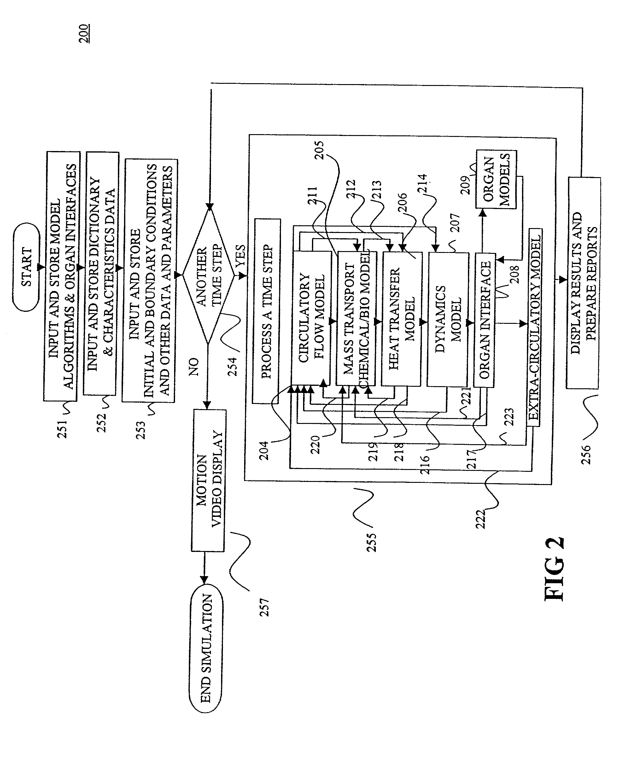
A method of simulating a bio-transport system comprising: (a) characterizing one or more elements to represent a bio-transport system of an organism or a portion thereof; (b) constructing one or more mathematical representations that model one or more bio-transport dynamics for each element based on the characterization of the elements to form a configured simulation model; (c) initializing the configured simulation model; (d) executing the configured simulation model to obtain bio-transport dynamics data for one or more elements; and (e) outputting information to a user based on at least a portion of the bio-transport dynamics data.

Description

[0001] This application is a Continuation of application Ser. No. 09 / 353,301, filed Jul. 13, 1999 which is a Continuation-in-Part of Application No. 60 / 092,608, filed Jul. 13, 1998 entitled "Circulatory System Simulator."[0002] This invention relates to a computer-based simulation model for simulating a transport system in an organism. More specifically, the present invention relates to a configurable simulation model that emulates the behavior of a circulatory system.[0003] Almost all organisms have systems for channeling or otherwise controlling the movement of mass and / or energy in or around the organism. These systems are referred to herein as "bio-transport systems" (BTS), and include, for example, circulatory systems, digestive (gastrointestinal) systems, pulmonary systems, lymphatic systems, renal systems, and the movement of chemical and biological entities within and among tissues and cells just to name a few.[0004] One bio-transport system of particular interest herein is ...

Claims


Application Information

Patent Timeline
Patent Type & Authority Applications(United States)
IPC IPC(8): G06N3/00
CPCB82Y10/00G06N3/002
Inventor KEANE, JOHN A.
Owner KEANE JOHN A
Learn More