Rapid fluid cooling and heating device and method

a fluid cooling and heating device technology, applied in domestic cooling apparatus, container discharging methods, lighting and heating apparatus, etc., can solve the problems of increasing cooling lag time, inability to meet the needs of conventional refrigeration and freezer units, and inordinate initial periods of time for cooling, so as to improve the frictional contact, prevent the container from hydroplaning on the roller, and the surface area of the container is large

Inactive Publication Date: 2002-09-12
THE COOPER UNION FOR THE ADVANCEMENT OF SCI & ART
View PDF0 Cites 79 Cited by
  • Summary
  • Abstract
  • Description
  • Claims
  • Application Information

AI Technical Summary

Benefits of technology

0032] A water jet of sufficient volumetric flow rate will tend to spread over the entire surface of the container even if it is limited to a small initial area of impingement on the container. Thus, water jet dispensing means, such as a shower head or spray jet is effectively provided directly above a portion of the container. The provision of the aforementioned contact rings on the roller enables the water to coat a greater surface area of the container than would be possible with a solid roller; i.e., the sprayed water clings to the container around the entire surface of the container--even the bottom-most portion--except where the contact rings engage the container. The contact rings also create much better frictional contact with the container than a simple solid roller and prevent hydroplaning of the container on the roller during rotation. Because of the angling of the profile of the ribs, the container moves closer to the rear of the housing towards the spray jet. The advantage is that the need for a number of spray jets is reduced, because the container is consistently and repeatably positioned within the cooling unit so that a single spray jet can cover the entire surface of the container.
0033] The housing is also preferably provided with a cut-out portion formed in a front end of the housing. The cut-out is provided to accommodate containers having long necks that may exceed the dimensions of the cooling unit. In this way, containers such as wine or beer bottles may be rapidly chilled by a device that need not be as large as to enclose an entire wine bottle. Manufacturing materials are saved, and costs are thus reduced. Moreover, the size of the device is reduced, thereby conserving kitchen counter space in a domestic setting. The provision of a cut-out further emphasizes the importance of angling the ribs to control the positioning of the container with respect to the spray jet. A splash guard may be removably provided to cover the cut-out portion so as to reduce the amount of the medium that exits the housing during operation.
0034] Optionally, the device includes timing means for showering the containers for a predetermined time sufficient to effect the requisite cooling or warming. The device may be preprogrammed with a set number of different timing sequences and / or rotational speeds depending on the type of container, the type of liquid / beverage, and the desired temperature of the liquid. The device may include a means for continuing the sequence beyond the predetermined period of time if the user wishes to provide extra cooling or warming for the liquid. Temperature sensors may be provided to monitor the reservoir, the liquid in the container, or both. The container sensors may be contact sensors, infrared sensors, or the like.

Problems solved by technology

While effective, such cooling means entails the utilization of massive refrigerator and freezer space (especially in commercial establishments) which is costly and is at a premium, particularly when freezer or refrigerator space is generally required for other food storage purposes.
In addition to occupying a lot of space, these conventional refrigeration and freezer units require inordinate initial periods of time to cool a liquid such as a beverage, for example, from room temperature (20.degree.-25.degree. C.) to the desired 5.degree. C., approximately an hour to several hours.
If reasonably immediate consumption is required, such as at point of sale, at parties, or on very hot days, this time delay for cooling is unacceptable.
Some of these devices, while generally effective in reducing the time for cooling beverages, nevertheless still require a minimum of about five minutes for the cooling of a standard 12 oz beverage can, still an inordinate amount of waiting time for a customer; this cooling lag time increases for larger containers, such as 16 oz or 20 oz soda or beer bottles and roughly 25 oz wine bottles.
However, the Chill Wizzard device can only chill 12 oz cans and is unable to accommodate a variety of different-sized or -shaped containers.
A second, less effective method involves conveying or placing the beverage containers into a cold water or bath.
Despite its effectiveness in cooling (because of its low temperatures relative to water), the use of ice as a direct cooling medium can however be detrimental in certain common uses.
When used for cooling carbonated beverages, particularly when such cooling is not carefully monitored, freezing of the beverage, with untoward consequences, is possible.
As a result, if the ice temperature is sufficiently low, freezing of the beverage within the container is possible, especially with extended cooling times. Since such containers are closed, it is difficult if not impossible to monitor temperature and phase conditions of the beverage during the cooling process to stop the process prior to any freezing.
Under these conditions, with excessive cooling, partially frozen carbonated beverages will erupt when the container is opened.
Though cold water is not subject to this detrimental effect with carbonated beverages, its use is however not as efficient in effecting the requisite rapid cooling.
In addition, none of the prior art devices discussed above can be used without major modification for other purposes, such as warming a beverage such as infant formula or making ice cream.
Yet the teachings of Loibl et al. in the '054 patent do not expressly address the need to accommodate a variety of different-sized and shaped containers.
Further, the prior Loibl device, while extremely effective, incorporates a number of spray jets positioned in various locations above the rotating containers and a number of rollers positioned below the containers.
Heating a baby bottle in this manner can cause the contents of the bottle to become extremely hot to the point of being dangerous.

Method used


Image

  • Rapid fluid cooling and heating device and method
  • Rapid fluid cooling and heating device and method
  • Rapid fluid cooling and heating device and method

Examples


Embodiment Construction

will now be provided with reference to FIGS. 1-14. It should be understood that these drawings and this detailed description are exemplary in nature only, and do not serve to limit the scope of the invention, which is defined by the claims appearing hereinbelow.

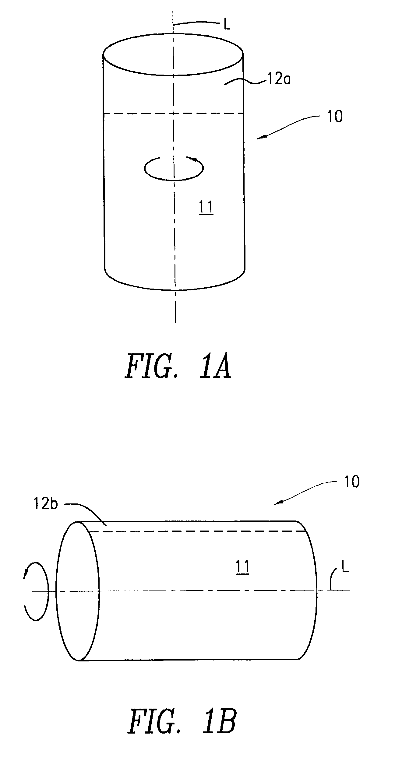
[0050] FIGS. 1A and 1B depict a typical 12 ounce beverage container 10 positioned vertically and horizontally respectively. The beverage 11, contained therein is shown with an air space 12A in FIG. 1A and a full can length air space 12B in FIG. 1A. Rotation of the container along its longitudinal axis L, when the container is positioned vertically, results in a rotation of an essentially rigid body with little mixing and extensive cooling times being required. By contrast, the horizontally disposed container 10 in FIG. 1B, when rotated about its longitudinal axis L, results in a high degree of agitation with a high degree of mixing and exchange heat transfer rates.

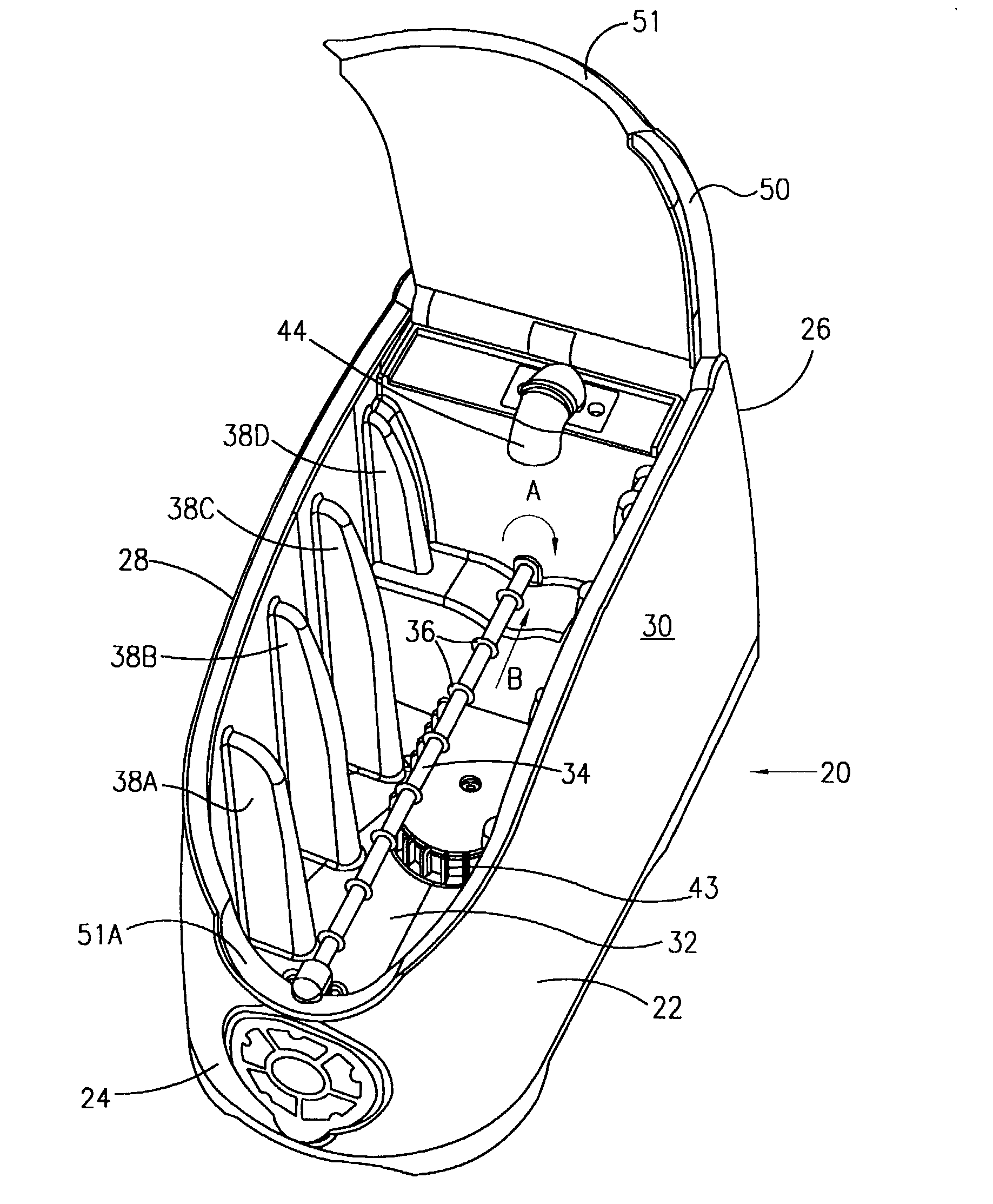
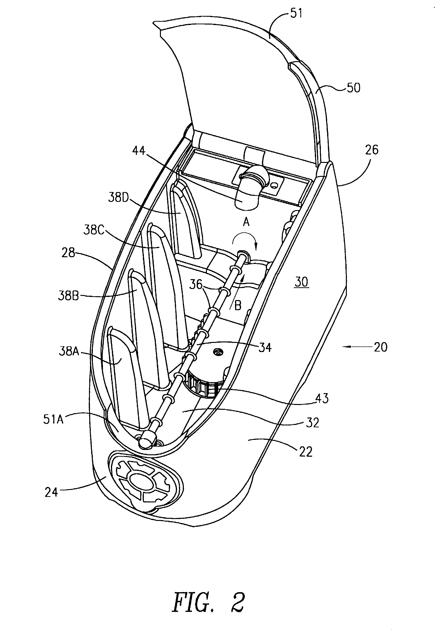
[0051] FIGS. 2-7 depict a preferred embodiment of the inventio...


PUM


Abstract

A method and device for rapidly changing at least one of the temperature and the state of a liquid in a container is provided. The container is rapidly rotated about its longitudinal axis. A source of a thin film of a medium having a different temperature than the liquid in the container is provided to thermally affect the container while rotating the container. The container is positioned at an angle to the horizontal of less than 45°, and the position of the container with respect to the thin film source is controlled by angling the axis of the container skewed from the axis of the rotating mechanism. The device can be used to cool liquids such as beverages, warm liquids such as infant formula, and/or make ice cream.

Description

[0001] This application claims domestic priority from U.S. Provisional patent application Ser. No. 60 / 272,510 filed Mar. 1, 2001 and incorporates by reference all of the teachings therein.[0002] 1. Field of the Invention[0003] This invention relates to methods and devices for use in the rapid cooling and heating of fluids in various containers of differing geometry.[0004] 2. Description of the Related Art[0005] Various devices and methods have been employed in cooling beverages or fluids in containers from room temperature to consumption-pleasing low temperatures, generally of about 5.degree. C. The most common method is the use of commercial or household refrigerators or freezer units into which the beverage containers are statically placed. Air inside the conventional refrigerator or freezer is cooled, and the air cools the beverages or fluids. While effective, such cooling means entails the utilization of massive refrigerator and freezer space (especially in commercial establishm...

Claims


Application Information

Patent Timeline
Patent Type & Authority Applications(United States)
IPC IPC(8): A23G9/22F25B21/04F25D3/02F25D3/10F25D11/00F25D17/02F25D31/00F28D3/00F28D11/02
CPCF25B21/04F25D3/02F25D3/10F25D31/007F25D2400/06F25D2400/28F28D3/00F28D11/02
Inventor LOIBL, GREGORY H.SIDEBOTHAM, GEORGE
Owner THE COOPER UNION FOR THE ADVANCEMENT OF SCI & ART
Why Eureka
Try Eureka