Eureka AIR delivers breakthrough ideas for toughest innovation challenges, trusted by R&D personnel around the world.

Compensation for variable voltage

a variable voltage and compensation technology, applied in the direction of electric variable regulation, synchronous motor starters, instruments, etc., can solve the problems of dc link voltage that varies, experience a significant reduction in the ability to control the machine as demanded by the user, and degrade performan

Inactive Publication Date: 2002-09-12
NIDEC SR DRIVES
View PDF0 Cites 16 Cited by
  • Summary
  • Abstract
  • Description
  • Claims
  • Application Information

AI Technical Summary

Benefits of technology

0020] Given the disadvantages of known compensation systems, it is desirable to have a DC link voltage compensation system that is accurate, covers a wide range of DC link voltages and is relatively inexpensive. Embodiments of the invention achieve these and / or other advantages.

Problems solved by technology

However, changes in the voltage of the AC supply and changes in the electrical environment in which the drive system operates often result in a DC link voltage that varies over time.
Because the supply voltage can vary significantly, a control scheme that ignores changes in supply voltage may experience a significant reduction in ability to control the machine as demanded by the user.
This undesirable change in the flux in the motor can result in degraded performance.
This type of characterization is undesirable to the extent that it characterizes the switched reluctance drive to run in a worst-case scenario (which may seldom occur) rather than at the desired optimum DC link value, at which the efficiency of the drive would be at its highest.
In addition, an increase in operating voltage may increase the available torque and current to such an extent that components of the drive may overheat and fail.
For these drives, there must be some compensation for changes in the DC link voltage during operation or the drive will suffer diminished performance, particularly at low supply voltages.
This makes the prior art compensation methods unsuitable in many circumstances.
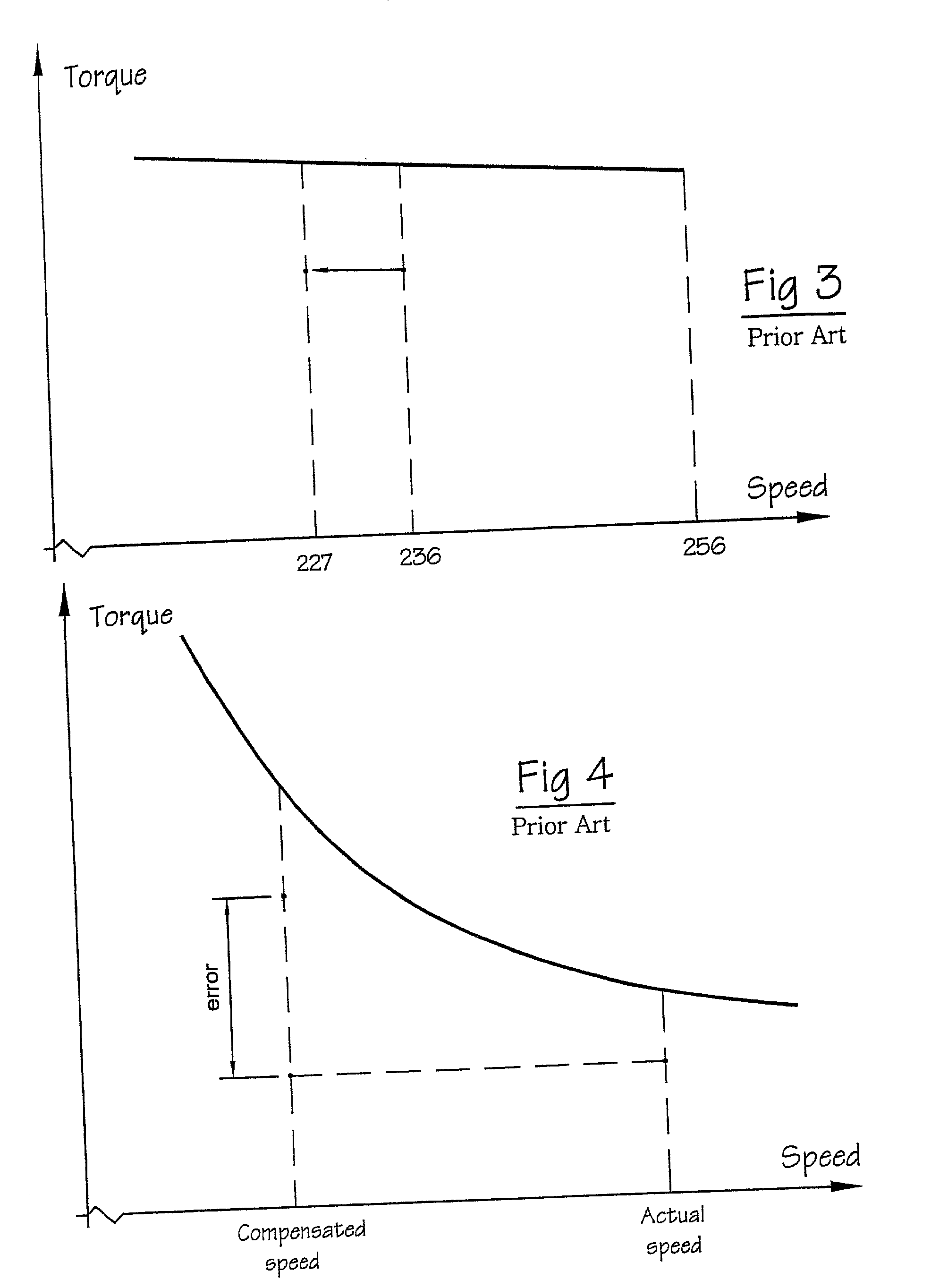
While the above-described systems can work well over a limited range of voltage variation, depending on the form of the torque / speed curve, they do not give good results when widely varying voltages are encountered.
While these variations could be partially catered for by characterizing the system at different voltages, this is expensive in development time, requires considerably more storage space in the control system, makes reading the control laws more difficult and, at best, gives accurate compensation only at certain voltages.

Method used


Image

  • Compensation for variable voltage
  • Compensation for variable voltage
  • Compensation for variable voltage

Examples


Embodiment Construction

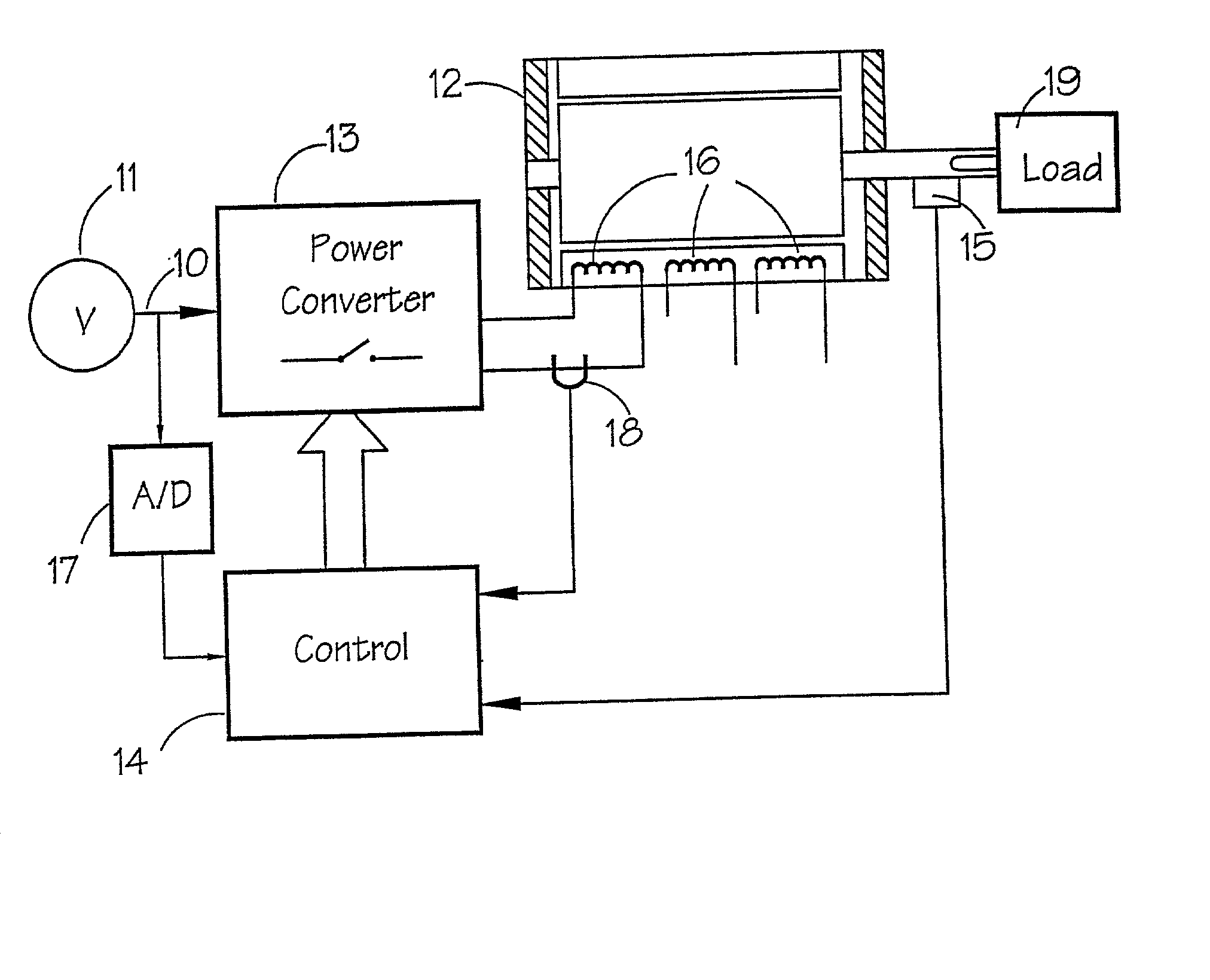
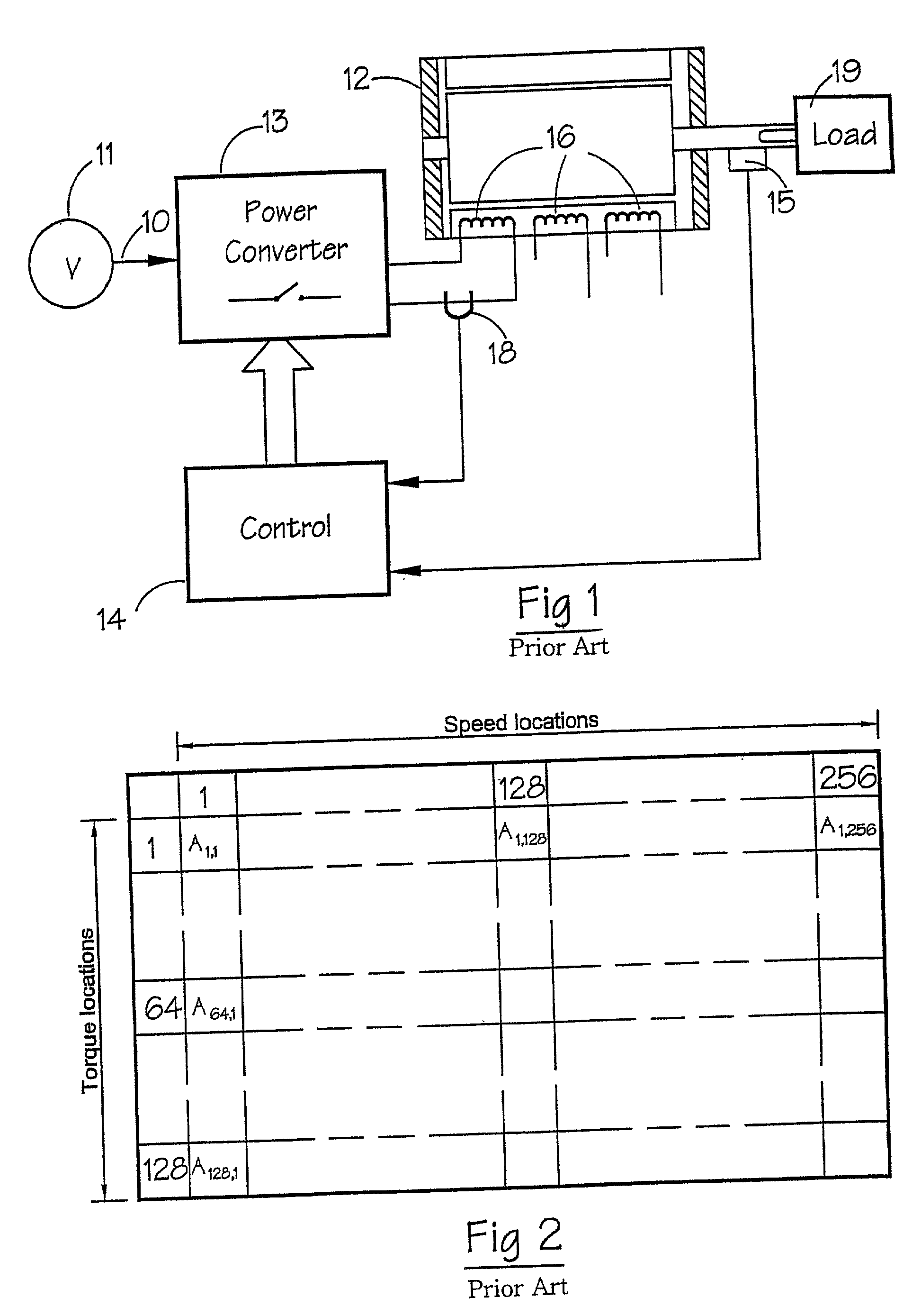
[0028] FIG. 5 shows a representation of a switched reluctance machine in which embodiments of the invention can be implemented. The machine of FIG. 5, for example, can be used to implement methods of voltage compensation according to embodiments of the invention. A switched reluctance machine 12 drives a load 19. The drive is supplied from voltage source 11, which can be a DC source or a rectified AC source. The DC link is represented by the connection 10 and is switched by switch means 13 to the phase windings 16 of the machine 12. A controller 14 determines the firing angles for the switch means 13. Also included is a rotor position sensor 15 (RPT), which is influenced by a member attached to rotate with the rotor of the machine 12, for creating a rotor position sensor output signal representative of the position of the rotor. It will be appreciated that position information can be derived by alternative means, including a software algorithm which estimates the information from mo...


PUM


Abstract

A switched reluctance drive is supplied from a voltage source which varies from the voltage at which the control laws for the drive were determined. The control system compensates for this by modifying both the speed and torque values used to determine the correct firing angles for the demanded load. The system works over a very wide range of voltage variation and is independent of the shape of the torque / speed curve of the drive.

Description

CROSS-REFERENCE TO RELATED APPLICATION[0001] The subject matter of this application is related to the subject matter of British Patent Application No. GB 0105502.9, priority to which is claimed under 35 U.S.C. .sctn.119 and which is incorporated herein by reference.BACKGROUND OF THE INVENTION[0002] 1. Field of the Invention[0003] Embodiments of the present invention generally relate to an apparatus and method of compensating for DC link voltage variations in an electric drive system. More particularly, embodiments of the present invention relate to the operation of a switched reluctance drive that periodically reads a value corresponding to a DC link voltage and adjusts a speed indication signal to compensate for changes in the DC link voltage. The compensated speed signal is transmitted to a controller where it is used to compensate the energization of the windings of the switched reluctance drive.[0004] 2. Description of Related Art[0005] The general theory of the design and opera...

Claims


Application Information

Patent Timeline
Patent Type & Authority Applications(United States)
IPC IPC(8): H02P25/08
CPCH02P25/08Y10S388/902
Inventor MCCLELLAND, MICHAEL LEOQUINN, JONATHAN RICHARD
Owner NIDEC SR DRIVES
Why Eureka
Eureka Blog
Learn More