
Optical transmission apparatus for multiple wavelengths and optical transmission wavelength control method

a transmission apparatus and optical transmission technology, applied in multiplex communication, semiconductor lasers, instruments, etc., can solve the problems of increasing cost, affecting the transmission quality, and difficult to bring such optical communication into practical use, so as to avoid the occurrence of inter-channel crosstalk

Inactive Publication Date: 2002-09-12
FUJITSU LTD
View PDF0 Cites 17 Cited by
  • Summary
  • Abstract
  • Description
  • Claims
  • Application Information

AI Technical Summary

Benefits of technology

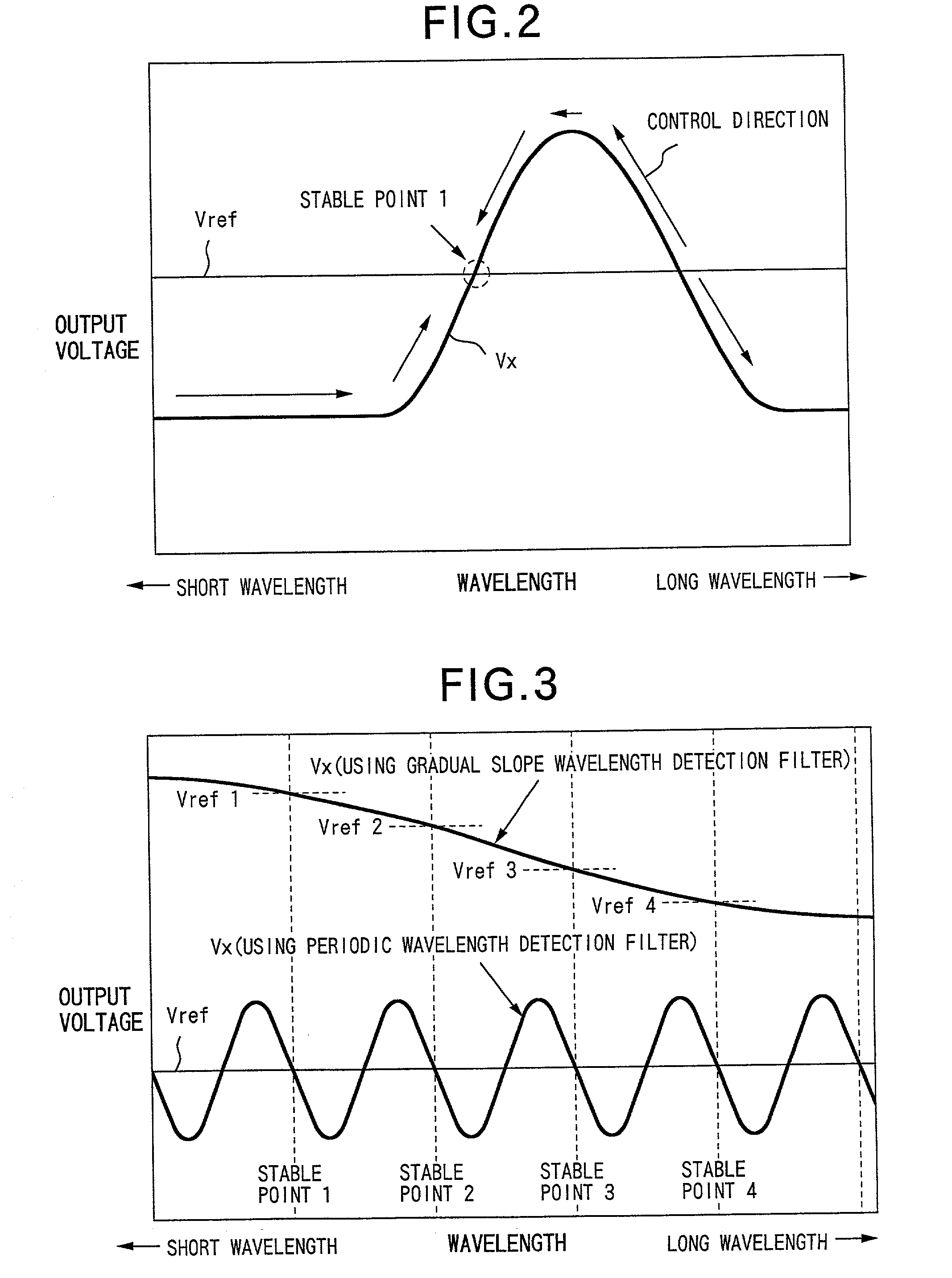
[0011] Furthermore, in the optical transmission apparatus for multiple wavelengths, the wavelength detection filter preferably has a periodic transmission wavelength characteristic. By using such a wavelength detection filter, a wavelength deviation due to circuit errors and the like becomes small, and hence the wavelength control is accurately performed.
[0013] By having such a construction, the control direction of the capture operation can be selected in accordance with the set target wavelength. Therefore, the stable points of the wavelength control can be doubled.
[0015] With such a construction, the operation of the temperature control means is not controlled by a multiple loop construction of the temperature control loop and the wavelength control loop, so that a wavelength control time until the optical output wavelength becomes stable is shortened.
[0018] With such a construction, an influence on the wavelength control due to the occurrence of wavelength drift is reduced, enabling an even more accurate wavelength control.
[0020] With such a construction, since the optical output is shut off at the time of wavelength control transition, the occurrence of inter-channel crosstalk can be avoided.

Problems solved by technology

However, with an ultra high transmission speed, it has become technically difficult to bring such optical communication into practical use.
Furthermore, an increase in cost has been resulted.
However, if the wavelength of the optical signal output from the optical transmission apparatus and the like is deviated from the transmission central wavelength of the narrow-band optical filter, the optical output power is attenuated by the narrow-band optical filter, and thus reduced so that transmission quality is degraded.
However, these optical devices suffer from problems in manufacturability and availability.
Furthermore, since the wavelength control is limited to single fixed wavelengths only, this has the drawback of poor expandability on the user side.
In addition, if a backup configuration for dealing with failures and so forth is considered, this also becomes extremely disadvantageous cost-wise since the number of parts is further increased.

Method used


Image

  • Optical transmission apparatus for multiple wavelengths and optical transmission wavelength control method
  • Optical transmission apparatus for multiple wavelengths and optical transmission wavelength control method
  • Optical transmission apparatus for multiple wavelengths and optical transmission wavelength control method

Examples


first embodiment

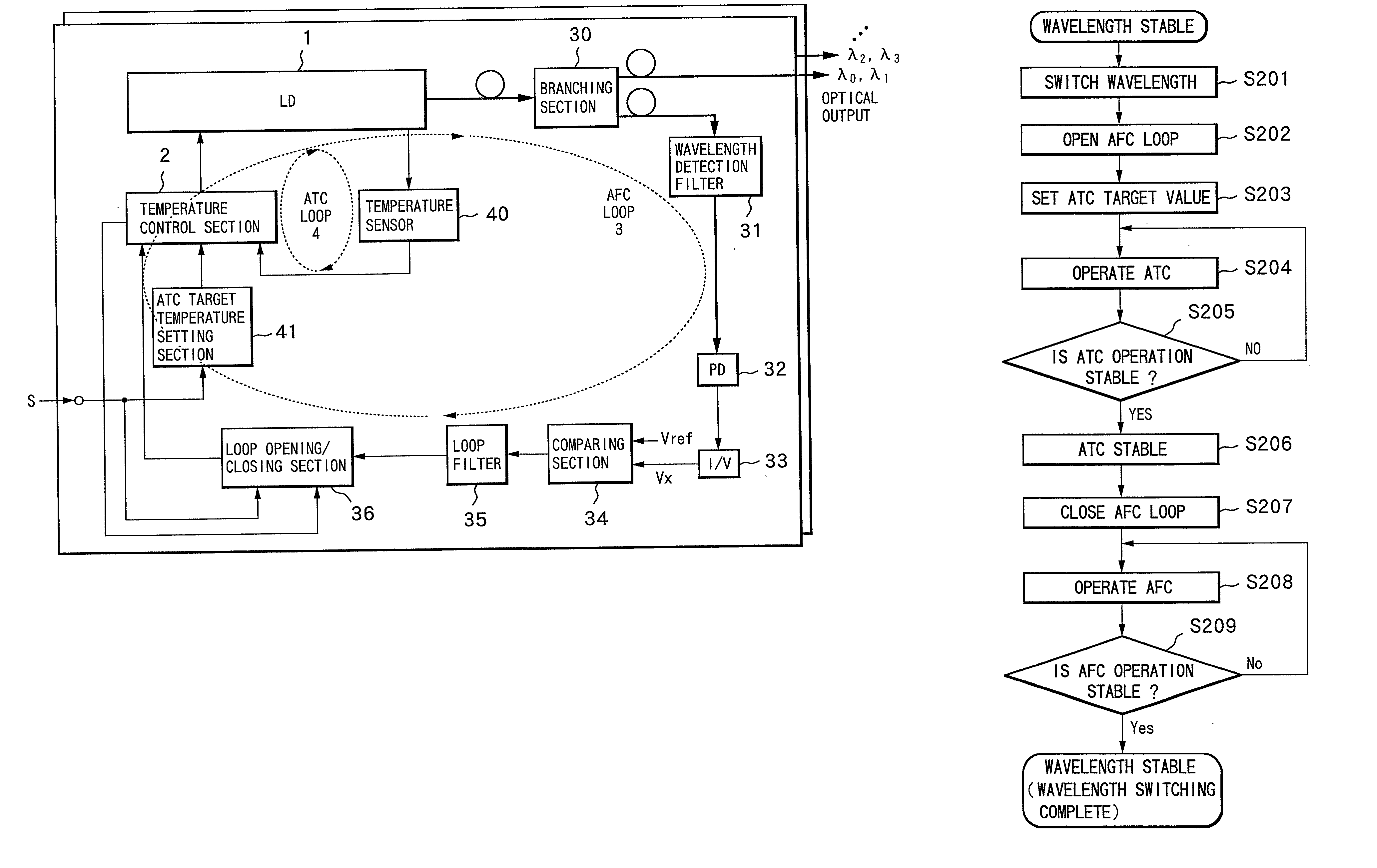
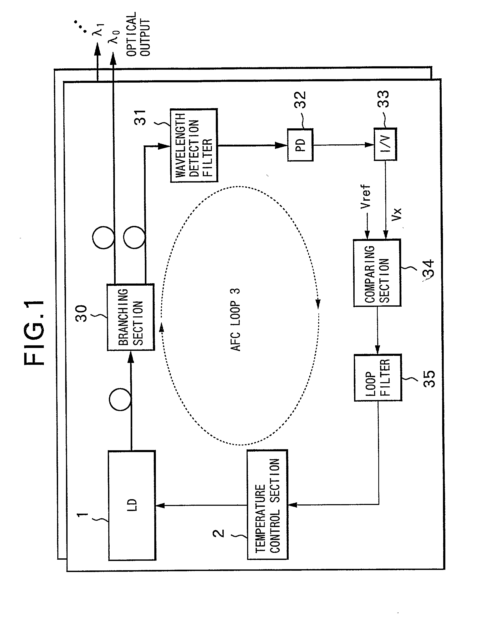
[0060] FIG. 5 is a block diagram showing a basic construction of an optical transmission apparatus of a Parts similar to the construction of the abovementioned typical optical transmission apparatus shown in FIG. 1 are denoted by the same reference numerals, and the same applies hereunder.

[0061] In FIG. 5, this optical transmission apparatus uses an optical filter having a periodic transmission wavelength characteristic, as the wavelength detection filter 31 of the AFC loop 3 in the typical optical transmission apparatus of FIG. 1, and is additionally provided with an automatic temperature control loop 4 (hereunder ATC loop 4) for detecting the temperature of the LD 1 and sending the detection result to the temperature control section 2 to make the LD 1 constant at a required target temperature. Furthermore, this optical transmission apparatus is provided with a loop opening / closing section 36 inside the AFC loop 3, so that the opening and closing of the AFC loop is possible.

[0062]...

second embodiment

[0087] Next is a description of an optical transmission apparatus of a

[0088] FIG. 12 is a block diagram showing a basic construction of the optical transmission apparatus of the second embodiment.

[0089] In FIG. 12, the part where the construction of this apparatus is different from the construction of the first embodiment is that a control polarity switch section 37 is provided inside the AFC loop 3. The construction of the other parts is the same as for the case of the first embodiment, and therefore the description thereof is omitted.

[0090] The control polarity switch section 37 is here inserted for example between the loop filter 35 and the loop opening / closing section 36, and has a function for switching the polarity of the AFC operation (the direction of wavelength capture control), depending on the wavelength setting signal S. FIG. 13, as with the aforementioned case of FIG. 6, shows a specific circuit configuration example of the second embodiment. In this configuration examp...

third embodiment

[0096] Next is a description of an optical transmission apparatus of a

[0097] In the abovementioned first and second embodiments, the AFC loop 3 and the ATC loop 4 are multiple loops for the temperature control section 2 that performs the temperature control of the LD 1. Therefore, the time constant for the loop filter 35 of the AFC must be delayed sufficiently with respect to the time constant for the loop filter 22 of the ATC so that the respective control operations of the AFC and the ATC do not interfere with each other. Hence, a comparatively long time is required until the optical output wavelength is stabilized. Therefore, in the third embodiment, a description is given of an improved optical transmission apparatus wherein the time until the wavelength stabilization is shortened.

[0098] FIG. 16 is a block diagram showing a basic construction of the optical transmission apparatus of the third embodiment.

[0099] In FIG. 16, this apparatus is provided with an ATC / AFC switching sect...


PUM


Abstract

The optical transmission apparatus for multiple wavelengths according to the present invention comprises; a light source, a temperature control section for controlling the temperature of the light source, a temperature control (ATC) loop for controlling the operation of the temperature control section, and a wavelength control (AFC) loop. The ATC loop detects the temperature of the light source and feedback controls the operation of the temperature control section, so that the optical output wavelengths of the light source fall within a wavelength capture range corresponding to a target wavelength of the AFC loop. The AFC loop has a wavelength detection filter having a periodic transmission wavelength characteristic. After the operation of the ATC loop has stabilized, a wavelength capture operation is commenced, and the operation of the temperature control section is controlled so that the optical output wavelength of the light source is captured at a stable point corresponding to a target wavelength, among a plurality of stable points.

Description

[0001] This application is a continuation of PCT / JP99 / 03561 filed on Jul. 1, 1999.TECHNICAL FIELD[0002] The present invention relates to an optical transmission apparatus and an optical transmission wavelength control method, used in wavelength division multiplexed (WDM) optical transmission systems. In particular, the invention relates to an optical transmission apparatus for multiple wavelengths, which can switch and transmit optical signals of a plurality of wavelengths, and an optical transmission wavelength control method.BACKGROUND ART[0003] With recent high information orientation, in optical communication, a significant increase in transmission capacity together with a reduction in transmission cost is required. In order to meet these requirements, up until now a transmission speed has mainly been increased. However, with an ultra high transmission speed, it has become technically difficult to bring such optical communication into practical use. Furthermore, an increase in c...

Claims


Application Information

Patent Timeline
IPC IPC(8): H04J99/00H01S3/131H01S5/068H01S5/0687H04B10/07H04B10/293H04B10/40H04B10/50H04B10/564H04B10/572H04B10/60H04J14/02
CPCH01S3/1317H01S5/06804H01S5/0687H04B10/506H04B10/572H04J14/02
Inventor KUWAHARA, HIROSHINAGASE, NORIOMISAIZU, SETSUOKIYONAGA, TETSUYAOTSUKA, TOMOYUKISEKIYA, MOTOYOSHI
Owner FUJITSU LTD
Learn More