
Driving device, light amount controller and shutter

a technology of light amount controller and driving device, which is applied in the direction of program control, dynamo-electric converter control, instruments, etc., can solve the problems of increasing the outer dimensions of the motor, unable to effectively act on the magnetic flux generated by energizing the stator coil, and difficulty in utilizing this portion for other purposes, etc., to achieve easy manufacturing and high output

Inactive Publication Date: 2002-09-12
CANON KK
View PDF7 Cites 14 Cited by
  • Summary
  • Abstract
  • Description
  • Claims
  • Application Information

AI Technical Summary

Benefits of technology

[0016] It is a first object of the present invention to provide a small-sized and slim driving device which is easy to manufacture and capable of producing high output.
[0017] It is a second object of the present invention to provide a light amount controller using a small-sized and slim driving device which is easy to manufacture and capable of producing high output.
[0018] It is a third object of the present invention to provide a shutter using a small-sized and slim driving device which is capable of changing a diaphragm value and capable of producing high output.

Problems solved by technology

Similarly, the light controller proposed in Japanese Patent Publication (Kokoku) No. 53-2774 and the hollow motor proposed in Japanese Laid-Open Patent Publication (Kokai) 57-166847 each have stator coils and stator yokes arranged around a rotor magnet, so that the outer dimensions of the motor are increased, and magnetic flux generated by energization of the stator coils does not effectively act on the rotor magnet.
In addition, a central portion of the motor is occupied by the coils and the magnet, it is difficult to utilize this portion for some other purposes.
However, in the shutter device, a magnetic neutral point thereof is utilized to control the position of the shutter blade for an intermediate aperture, which makes it difficult to operate the blade with high accuracy.

Method used


Image

  • Driving device, light amount controller and shutter
  • Driving device, light amount controller and shutter
  • Driving device, light amount controller and shutter

Examples


second embodiment

[0105] Next, a light amount controller according to the present invention will be described in detail with reference to FIGS. 6 to 8B.

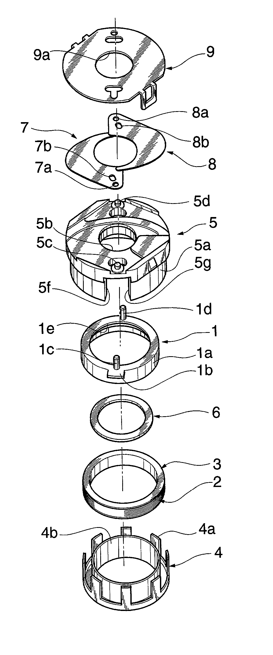
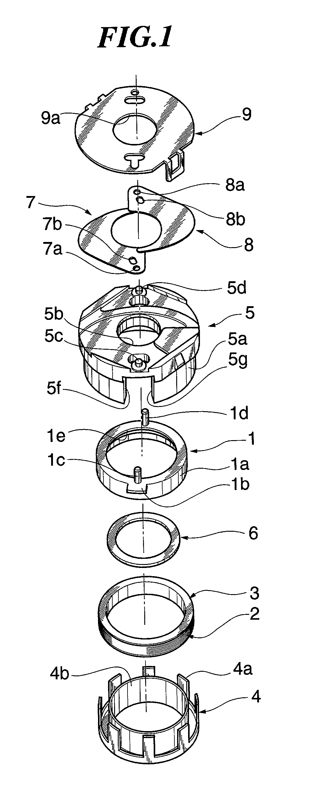
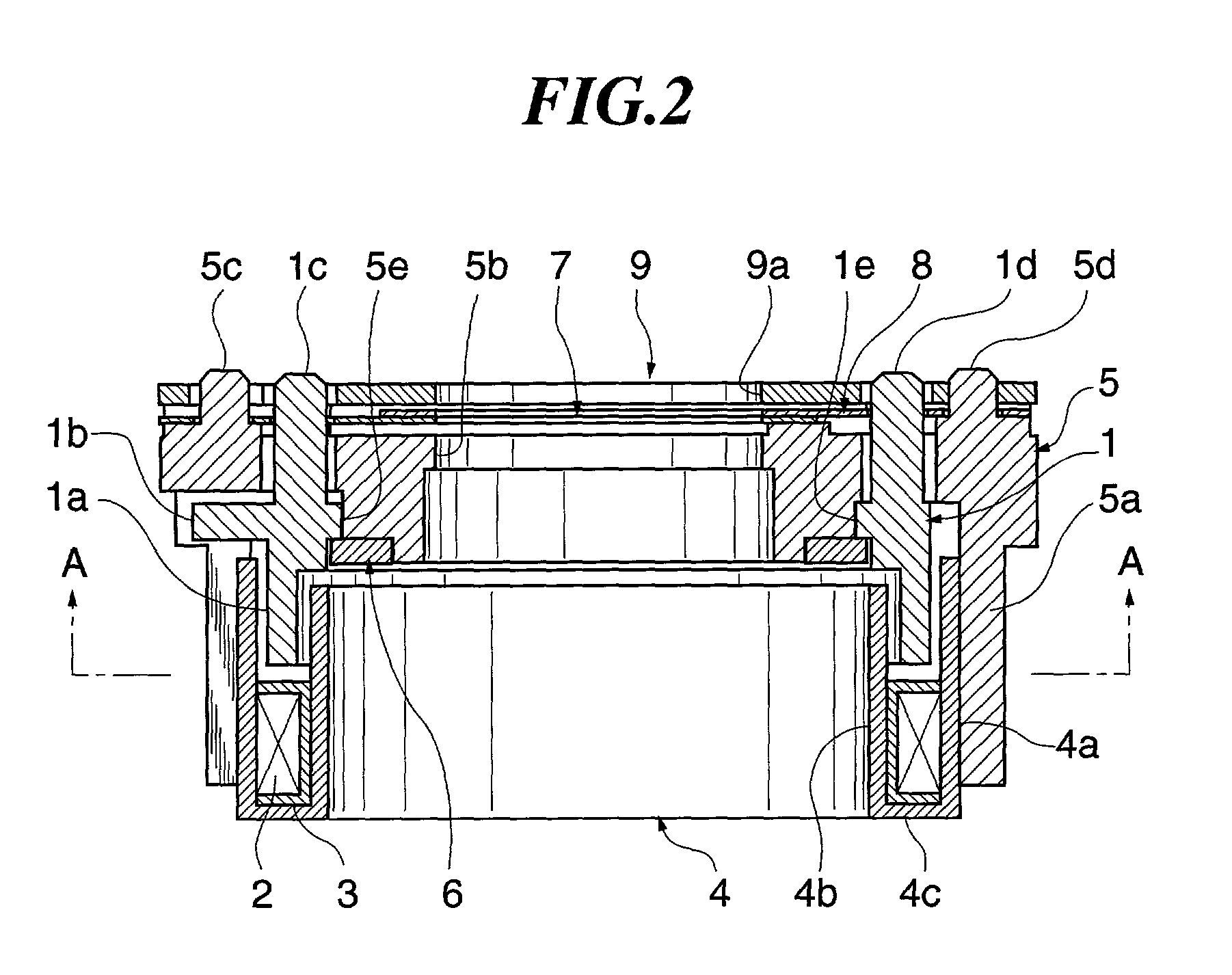
[0106] FIGS. 6 to 8B show the light amount controller according to the second embodiment. FIG. 6 is an exploded perspective view of the light amount controller equipped with a driving device according to the second embodiment. FIG. 7 is an axial cross-sectional view of an assembled state of the light amount controller equipped with the driving device shown in FIG. 6, while FIGS. 8A, 8B are views useful in explaining rotating operations of a magnet of the driving device. In these figures, component elements and parts corresponding to those in the first embodiment are designated by identical reference numerals.

[0107] The light amount controller of the second embodiment is identical in construction to the light amount controller of the first embodiment, except for the construction of a stator 4 thereof, described hereafter.

[0108] The stator 4 is configur...

third embodiment

[0112] Next, a shutter according to the present invention will be described in detail with reference to FIGS. 9 to 15.

[0113] FIGS. 9 to 15 show the shutter according to the third embodiment. FIG. 9 is an exploded perspective view of the shutter. FIG. 10 is an axial cross-sectional view of an assembled state of the FIG. 9 shutter, and FIGS. 13 to 15 are views useful in explaining rotating operations of a magnet of the FIG. 9 shutter.

[0114] In the shutter of the third embodiment, component elements and parts designated by numerals from 1 to 6 are identical in construction to those of the light amount controller of the first embodiment, and therefore are designated by identical reference numerals, and a description will be given of only different component elements of the shutter which distinguish the shutter from the light amount controller of the first embodiment.

[0115] In the following description, it is assumed that a rotational angle through which the magnet 1 can rotate between a...

first embodiment

[0125] When the coil 2 is not energized, the magnet 1 is held in any of the above states, just as in the

[0126] In the third embodiment, similarly to the first embodiment, the stopper portion 5f for limiting rotation of the magnet 1 is formed in the base board 5 as shown in FIG. 13, and the angle formed about the rotational axis 1f of the magnet 1 between the center of a magnetized pole of the magnet 1 and the center of the corresponding outer magnetic pole piece 4a when the projection 1b of the magnet 1 is in abutment with the stopper portion 5f, is set to a degrees. As a result, when the coil 2 is energized in the FIG. 13 state to magnetize the outer magnetic pole piece 4a, a rotational force is generated in the magnet 1, whereby the shutter is stably started.

[0127] The position of the magnet 1 in the FIG. 13 state corresponds to the point G in FIG. 4. Cogging torque acting on the magnet 1 at this position is T2. The cogging torque acts as a reverse rotational force (a force acting...


PUM


Abstract

There is provided a small-sized and slim driving device which is easy to manufacture and capable of producing high output. A magnet has a cylindrical shape, and at least the outer peripheral surface of the magnet is circumferentially divided into n sections magnetized so as to have alternately different poles. The magnet can rotate about a rotational axis of the cylindrical shape. A coil is arranged axially of the magnet and parallel thereto. An outer magnetic pole portion is disposed to be magnetized by the coil, and has a plurality of hair comb tooth-shaped portions opposed to the magnet and arranged around the magnet such that an angle corresponding to the circumferential width of each of the hair comb tooth-shaped portions opposed to the magnet about the rotational axis of the hollow cylindrical shape of the magnet is equal to a predetermined angle A. An inner magnetic pole portion is disposed to be magnetized by the coil, and has a hollow cylindrical shape opposed to the inner peripheral surface of the magnet. The predetermined angle A is set to such a value that a rotational force acts on the magnet to return to a position in which a circumferential center of each of n magnetized sections on the outer peripheral surface of the magnet is opposed to a circumferential center of a corresponding one of the hair comb tooth-shaped portions of the outer magnetic pole portion, when the circumferential center of each of n magnetized sections shifts from the position.

Description

BACKGROUND OF THE PRESENT INVENTION[0001] 1. Field of the Present Invention[0002] The present invention relates to a driving device having an extremely compact size, and a light amount controller and a shutter using the driving device.[0003] 2. Description of the Related Art[0004] Conventionally, motors that can be designed compact in size include a brushless motor. Brushless motors with simple driving circuits include a stepper motor, described below.[0005] FIG. 17 shows an example of a small-sized hollow cylindrical stepper motor. The stepper motor includes two stators 102 each comprised of a bobbin 101 having a stator coil 105 concentrically wound thereon, two stator yokes 106 axially fixedly holding the bobbin 101 in a sandwiching fashion, the stator yokes 106 each having stator teeth 106a and 106b alternately arranged circumferentially of an inner peripheral surface of the bobbin 101, and a casing 103 to which are secured the stator yokes 106 formed integrally with the respecti...

Claims


Application Information

Patent Timeline
Patent Type & Authority Applications(United States)
IPC IPC(8): H02K29/00G03B9/08
CPCG03B9/08H02K29/00
Inventor MIZUMAKI, MASAOAOSHIMA, CHIKARA
Owner CANON KK
Learn More