Fuel cell stack

Inactive Publication Date: 2002-09-12
HONDA MOTOR CO LTD
View PDF0 Cites 10 Cited by
  • Summary
  • Abstract
  • Description
  • Claims
  • Application Information

AI Technical Summary

Benefits of technology

0030] In the fuel cell stack which has the above structure, because the terminal element is located at a location where the difference between the saturated water vapor pressure and the partial p

Problems solved by technology

However, the modified structure contains a problem, as will be further explained below, due to significant heat dissipation from the terminal plat

Method used


Image

  • Fuel cell stack
  • Fuel cell stack
  • Fuel cell stack

Examples


Embodiment Construction

[0043] The preferred embodiments of the present invention will be explained with reference to the accompanying drawings.

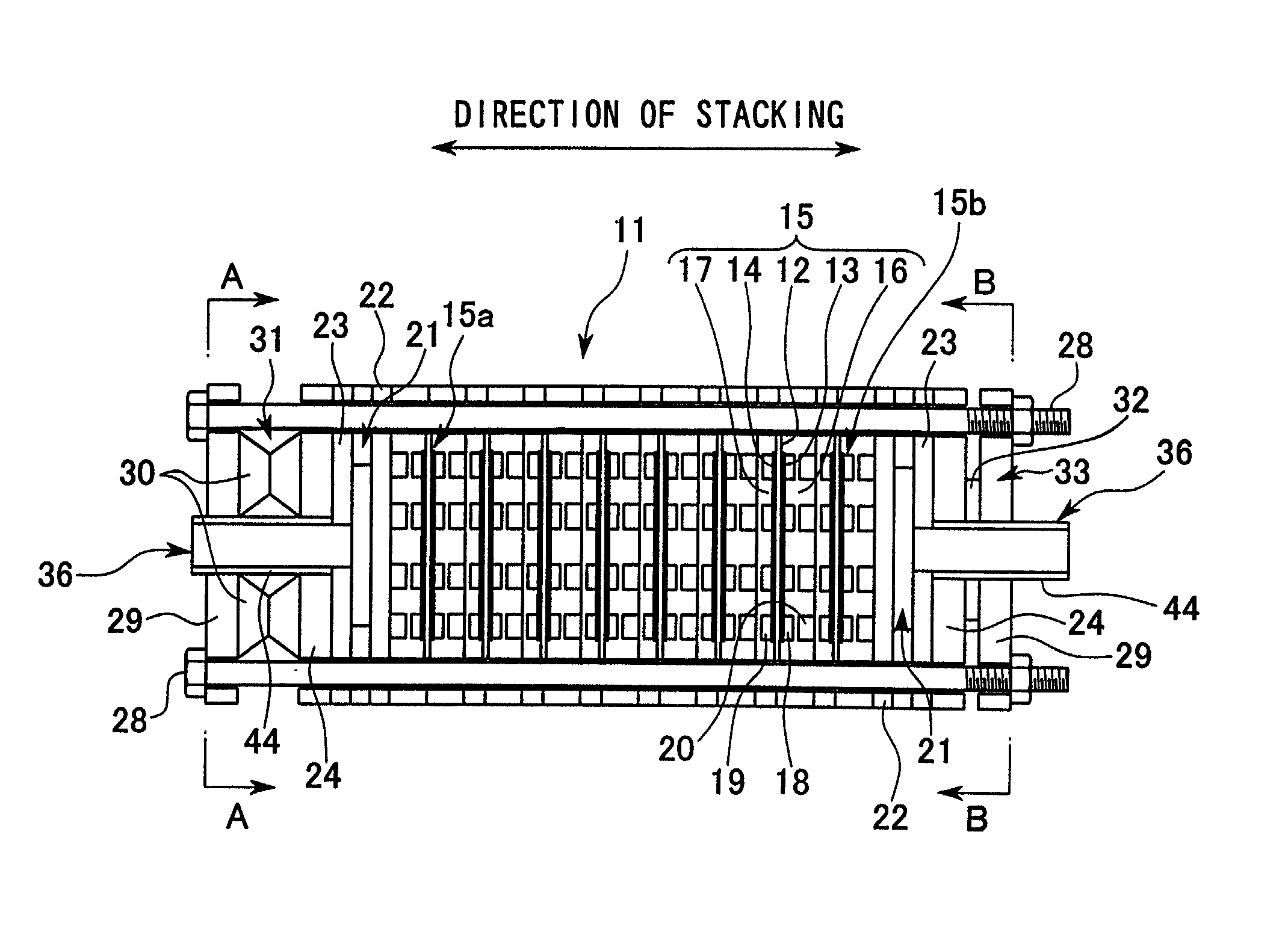
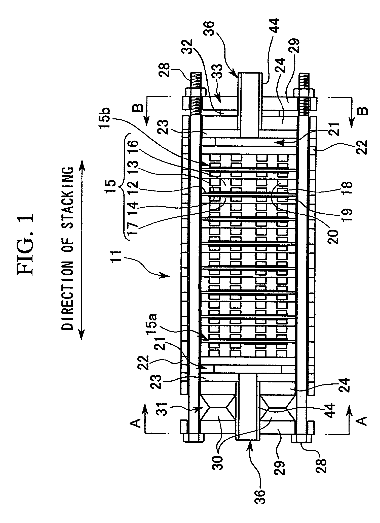
[0044] In FIG. 1, reference symbol 11 indicates a fuel cell stack which is to be used in a vehicle.

[0045] The fuel cell stack 11 is a so-called solid polymer electrolyte fuel cell stack comprising a plurality of fuel cell units 15 stacked together in the horizontal direction each of which comprises a solid polymer electrolyte membrane 12, i.e., an electrolyte, an anode electrode 13 and a cathode electrode 14 which together hold the solid polymer electrolyte membrane 12 therebetween, and a pair of separators 16 and 17 holding the anode electrode 13 and the cathode electrode 14 therebetween.

[0046] Passages 18 for allowing a fuel gas, e.g., hydrogen, to flow are formed between the anode electrode 13 and the separator 16 adjacent to the anode electrode 13. Passages 19 for allowing an oxidizing gas, e.g., an oxygen-containing gas or air, to flow are formed between the c...


PUM


Abstract

The present invention provides a fuel stack comprising: a plurality of fuel cell units stacked together in a direction of stacking each of which comprises an electrolyte element, a pair of electrodes holding the electrolyte element therebetween, and a pair of separators holding the electrodes therebetween; a pair of terminal plates each of which is disposed outside an end fuel cell unit located at an end of the stacked fuel cell units; and a terminal element extending outwardly in the direction of stacking from the outside surface of at least one of the terminal plates; wherein the location from which the terminal element extends is located within an area on the terminal plate, corresponding to an area in a passage for an oxidizing gas formed in the end fuel cell unit disposed adjacent to the terminal element where the partial pressure of water vapor is lower than the saturated water vapor pressure. More preferably, the terminal element is disposed as close to the centerline of the terminal plate as possible so that the total electrical resistance of the terminal element and the terminal plate is minimized. By this configuration, an increase in the total electrical resistance and water vapor condensation in the fuel cell units located at the ends of the stack may be prevented.

Description

BACKGROUND OF THE INVENTION[0001] 1. Field of the Invention[0002] This invention relates to a fuel cell stack, and more particularly relates to a technology which can prevent a degradation in the power generation performance of fuel cell units disposed at both ends of the fuel cell stack.[0003] 2. Background Art[0004] A solid polymer electrolyte fuel cell unit, as an example of a fuel cell, comprises: a solid polymer electrolyte membrane, i.e., a cation-exchange membrane; an anode electrode and a cathode electrode which together hold the solid polymer electrolyte membrane therebetween; and a pair of separators which hold the anode and cathode electrodes.[0005] A plurality of solid polymer electrolyte fuel cell units are stacked together to form a fuel cell stack for actual usage.[0006] In such a fuel cell stack, hydrogen gas, as an example of a fuel gas supplied to the anode electrode, is ionized on a catalytic electrode, and moves to the cathode electrode through the solid polymer ...

Claims


Application Information

Patent Timeline
IPC IPC(8): H01M2/14H01M8/02H01M8/10H01M8/24
CPCH01M8/0247H01M8/0263H01M8/2483H01M8/247H01M8/2457H01M8/241H01M8/0258H01M8/0267Y02E60/50
Inventor SUGITA, NARUTOSHIWARIISHI, YOSHINORIKOSHINUMA, MINORUKOMURA, TAKASHIONO, HIDEMITSU
Owner HONDA MOTOR CO LTD
Why Eureka
Try Eureka