

Method of fuel cell activation
a fuel cell and activation technology, applied in the field of fuel cells, can solve the problem that the activation form may not be feasibl
- Summary
- Abstract
- Description
- Claims
- Application Information
AI Technical Summary
Problems solved by technology
Method used
Image

Examples
example 1
[0058] A hydrogen storage alloy material is mixed with a hydrophobic binder and pasted onto a conductive substrate to form a hydrogen storage alloy electrode. The electrode has a geometric surface area of about 5.75 cm.sup.2 (i.e., length.times.width) and a total charge capacity C of about 0.246 amp-hours. The hydrogen storage alloy electrode is used as the hydrogen oxidation electrode (also commonly referred to as the anode) of an alkaline fuel cell. The potential of the hydrogen storage alloy electrode is measured relative to a mercury / mercury oxide reference electrode. A carbon-based electrode is used as the oxygen electrode of the test fuel cell. A third auxiliary electrode (for example, a nickel electrode) is used as the counter electrode for charging and discharging the hydrogen storage alloy electrode. Both the hydrogen storage alloy electrode as well as the nickel counter electrode are placed in contact with a KOH electrolyte. The hydrogen storage alloy electrode is first ch...
example 2
[0059] A hydrogen storage alloy material is mixed with a binder and compacted onto a conductive substrate to form a hydrogen storage alloy electrode. The electrode has a geometric surface area of about 5.75 cm.sup.2 and a total theoretical charge capacity of 0.1 amp-hours. The hydrogen storage alloy electrode is used as the anode of an alkaline fuel cell. The potential of the hydrogen storage alloy electrode is measured relative to a mercury / mercury oxide reference electrode. A carbon-based electrode is used as the oxygen electrode of the test fuel cell. A third auxiliary electrode (for example, a nickel electrode) is used as the counter electrode for charging and discharging the hydrogen storage alloy electrode. The hydrogen storage alloy electrode as the nickel counter electrode are placed in contact with an alkaline electrolyte. The hydrogen storage alloy electrode has a total charge capacity C of about 0.1 amp-hour. The hydrogen storage alloy electrode is first charged to a 41% ...
example 3
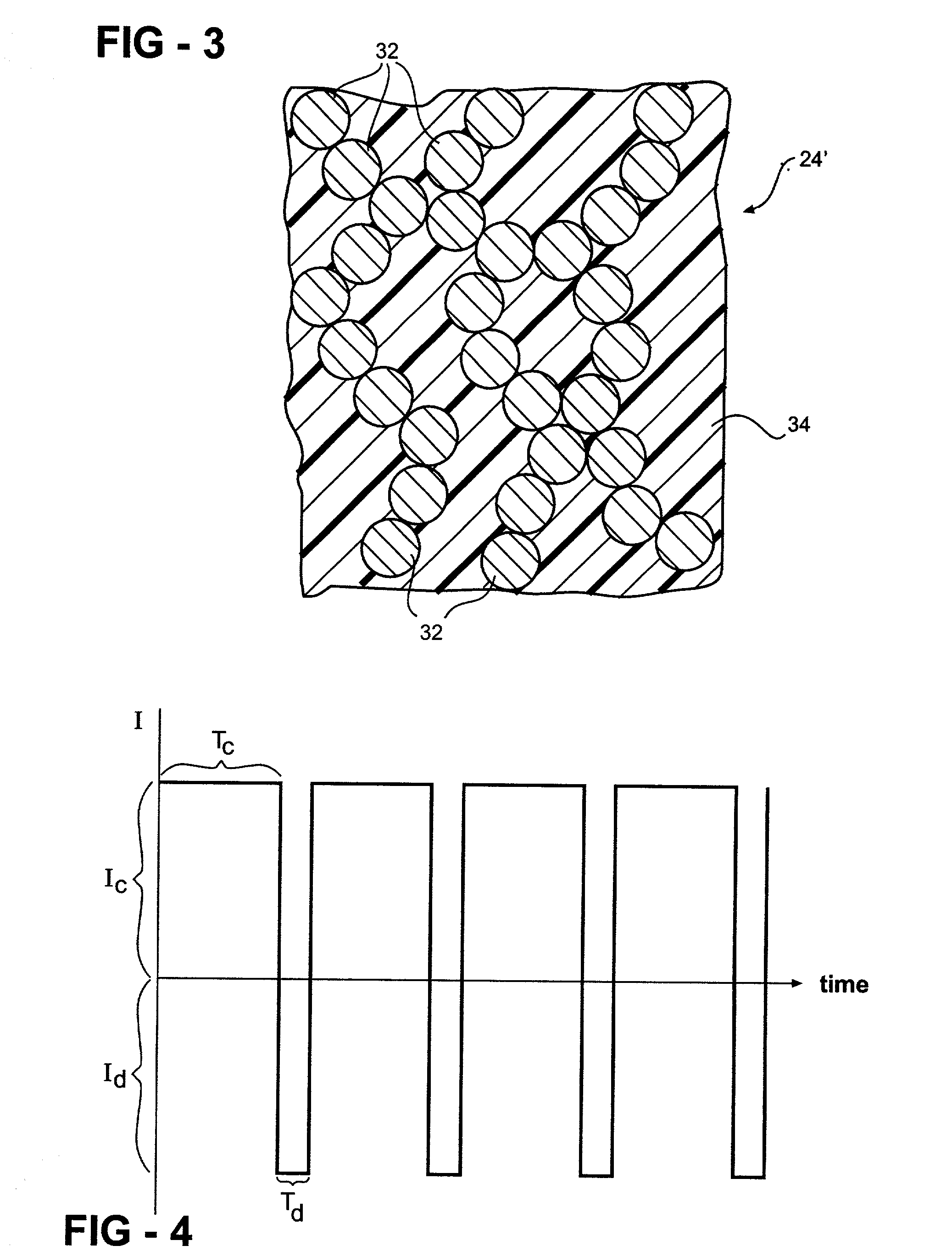
[0060] A hydrogen storage alloy material is mixed with a binder and compacted onto a conductive substrate to form a hydrogen storage alloy electrode. The hydrogen storage alloy electrode has a geometric surface area of about 100 cm.sup.2. The hydrogen storage alloy electrode is used as the anode of an alkaline fuel cell. The potential of the hydrogen storage alloy electrode is measured relative to a mercury / mercury oxide reference electrode. A carbon-based electrode is used as the oxygen electrode of the test fuel cell. A third auxiliary electrode (for example, a nickel electrode) is used as the counter electrode for charging and discharging the hydrogen storage alloy electrode. The hydrogen storage alloy electrode as the nickel counter electrode are placed in contact with an alkaline electrolyte. The fuel cell anode is activated with a 0.1 amp charge for 5 seconds (I.sub.c=0.1 amp and T.sub.c=5 seconds) and a 0.1 amp discharge for 2 seconds (I.sub.d=0.001 amps and T.sub.d=2 seconds...
PUM
| Property | Measurement | Unit |
|---|---|---|
| temperature | aaaaa | aaaaa |
| temperature | aaaaa | aaaaa |
| temperature | aaaaa | aaaaa |
Abstract
Description
Claims
Application Information