Damper based vehicle yaw control

Inactive Publication Date: 2002-09-12
BWI +1
View PDF0 Cites 48 Cited by
  • Summary
  • Abstract
  • Description
  • Claims
  • Application Information

AI Technical Summary

Benefits of technology

0019] The invention is a method for using controllable dampers to improve vehicle responses and stability during severe handling maneuvers. The method derives a total handling damping value for the vehicle and a control ratio of one of the front axle or rear axle roll damping to total roll damping for the vehicle in response to vehicle dynamic variables and further derives therefrom handling damping values for one or mo

Problems solved by technology

In these conditions, vehicle handling characteristics can change quite rapidly from those to which the driver is accustomed and affect the dr

Method used


Image

  • Damper based vehicle yaw control
  • Damper based vehicle yaw control
  • Damper based vehicle yaw control

Examples


Embodiment Construction

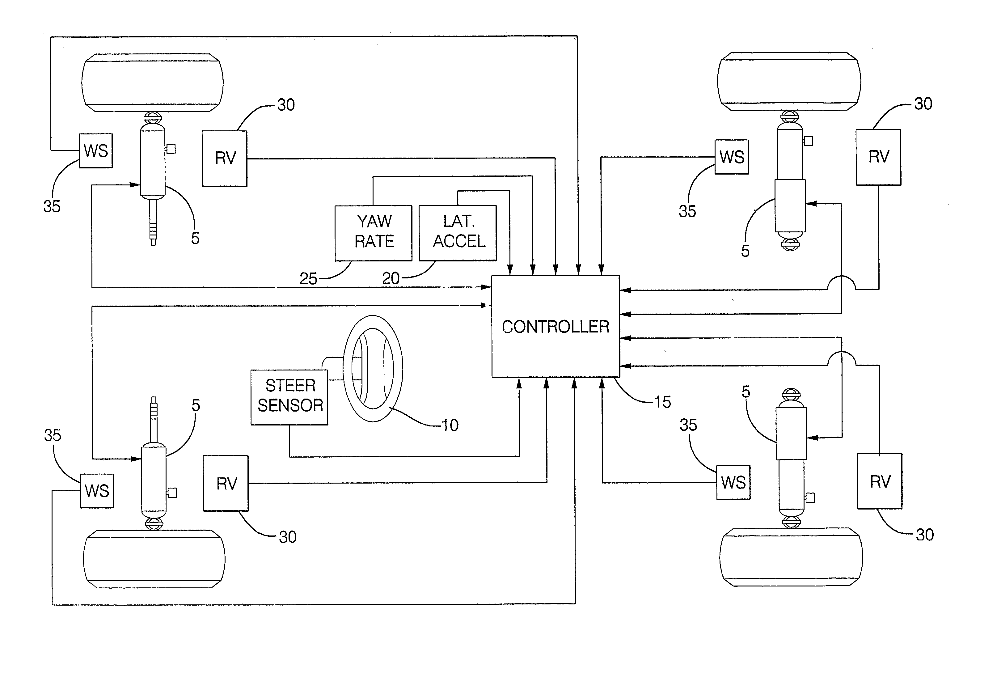
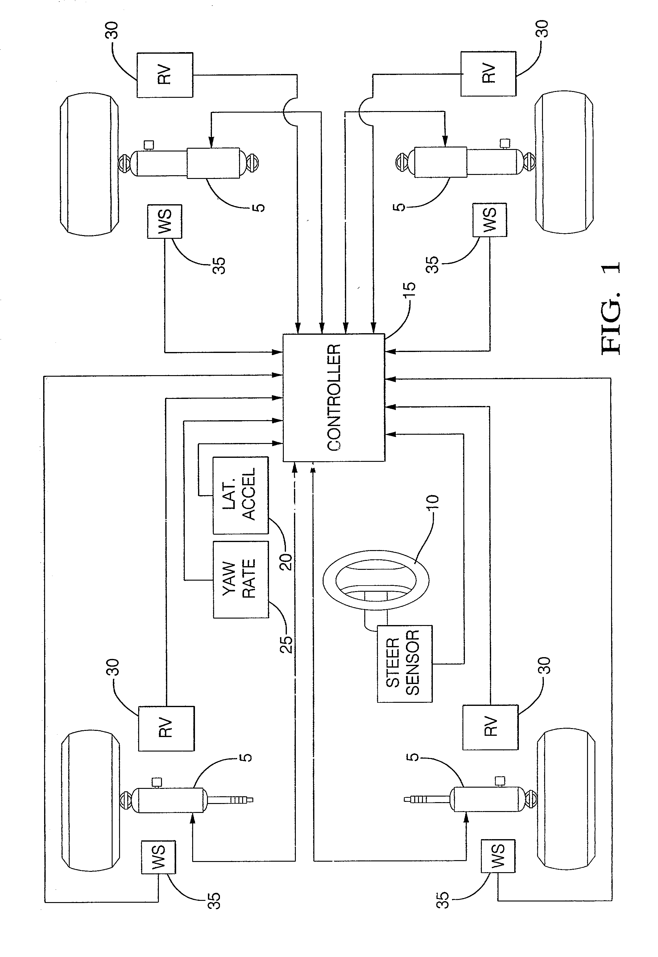
[0030] FIG. 1 details hardware used in a preferred embodiment of the damper based yaw control system of the present invention. There are shown at 5 the controllable dampers of the present invention. The controllable dampers are preferably controlled by an electric current applied to a coil controlling an orifice valve or a magnetorheological fluid so as to vary the damping force characteristic of the damper. Since such coils are preferably provided current switched in Pulse Width Modulation (PWM), this description uses the term PWM to indicate the percentage of full current provided and thus a commanded damping force characteristic, commonly referred to as a commanded "damping." There is also shown a steering sensor 10 for relaying steering information to the controller 15. There are also shown other sensors including a lateral acceleration sensor 20, yaw rate sensor 25, relative velocity sensor 30, and wheel speed sensor 35, that relay information to the controller 15.

[0031] As can...


PUM


Abstract

Controllable dampers are used to improve vehicle responses and stability during severe vehicle handling maneuvers. A total handling damping value for the vehicle is derived, preferably from the greatest of a yaw rate error value, a lateral acceleration value and a time derivative of lateral acceleration value. In addition, a control ratio of front axle roll damping to total roll damping is derived, preferably from the yaw rate error value, an oversteer/understeer indication and possibly vehicle speed. From these values, handling damping values are derived for each wheel of the vehicle and blended with damping values for the same wheels derived from suspension component movement to determine a corner damping command for each controllable damper. Preferably, the damping values derived from suspension component movement are shifted away from damping control of the vehicle body toward handling damping control when yaw rate error is large in magnitude.

Description

RELATED APPLICATION[0001] This is a Continuation-in-Part of U.S. Ser. No. 09 / 516,567, filed Mar. 1, 2000 and assigned to the assignee of this application.TECHNICAL FIELD[0002] The present invention relates to vehicle suspensions and the control thereof. More particularly, the present invention relates to a method of controlling a vehicle suspension by utilizing controllable dampers to distribute damping forces between front and rear axles.BACKGROUND OF THE INVENTION[0003] Several types of active control systems for vehicles have been employed to improve vehicle stability and handling by influencing tire forces in the horizontal (yaw) plane. Examples of such systems are active rear steer, active brake control of individual wheels, active suspensions, and active roll bars.[0004] Vehicle handling response to driver steering inputs is to a large extent determined by the forces between the tires and the road surface. During normal driving, tires remain within linear ranges of operation, ...

Claims


Application Information

Patent Timeline
IPC IPC(8): B60G17/016B60G17/0195B60G17/08
CPCB60G2800/212B60G2800/215B60G2800/24B60G2800/244B60G2800/246B60G2800/91B60G2800/922B60G17/0162B60G17/0195B60G17/08B60G2400/0523B60G2400/104B60G2400/208B60G2400/41B60G2400/822B60G2500/10B60G2600/184B60G2600/1873
Inventor BODIE, MARK OLENHAC, ALEKSANDER BOGUSLAW
Owner BWI
Why Eureka
Try Eureka