Fec frame structuring method and fec multiplexer

Inactive Publication Date: 2002-09-12
MITSUBISHI ELECTRIC CORP +1
View PDF5 Cites 24 Cited by
  • Summary
  • Abstract
  • Description
  • Claims
  • Application Information

AI Technical Summary

Benefits of technology

0033] Thus, only by adding the error correction means, without changing the structure of the FEC frame, it is possible to further en

Problems solved by technology

Thus, even when the radio of the error correction code to the target information was increased, it was imp

Method used


Image

  • Fec frame structuring method and fec multiplexer
  • Fec frame structuring method and fec multiplexer
  • Fec frame structuring method and fec multiplexer

Examples


first embodiment

[0045] (First Embodiment)

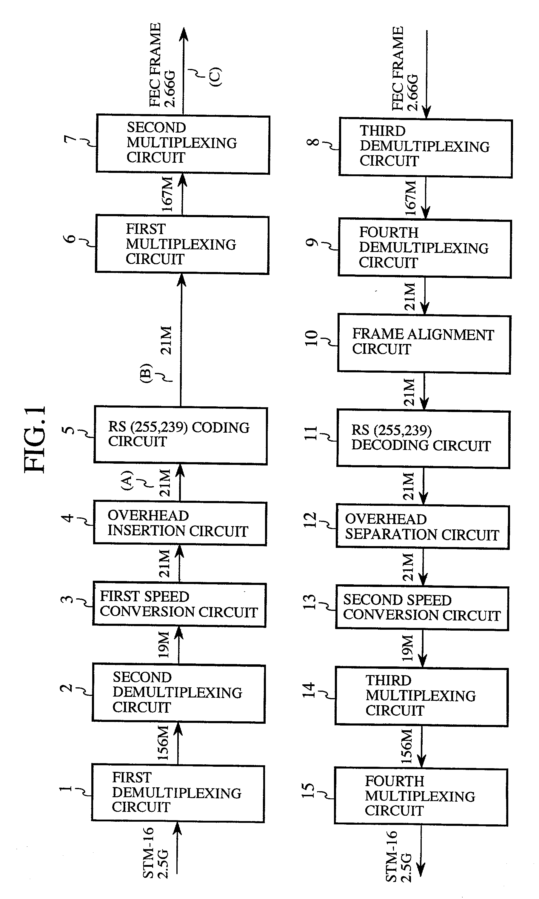
[0046] FIG. 4 is a schematic diagram showing an optical transmission system, to which an FEC frame structuring method and an FEC multiplexer according to the first embodiment of the invention are applied. In the drawing, a reference numeral 21 denotes a first optical receiver for receiving an STM-16 optical signal, and converting the optical signal into an electric signal; 22 an FEC multiplexing circuit (FEC multiplexer) for demultiplexing the electric signal from the first optical receiver 21, executing the insertion of overhead information, error correction coding, and so on, and then executing multiplexing again to structure an FEC frame; and 23 a first optical transmitter for converting the FEC frame into an optical signal. A reference numeral 24 denotes an optical transmission path for transmitting the FEC frame of the optical signal; 25 a second optical receiver for converting the FEC frame transmitted through the optical transmission path 24 from the ...

second embodiment

[0067] (Second Embodiment)

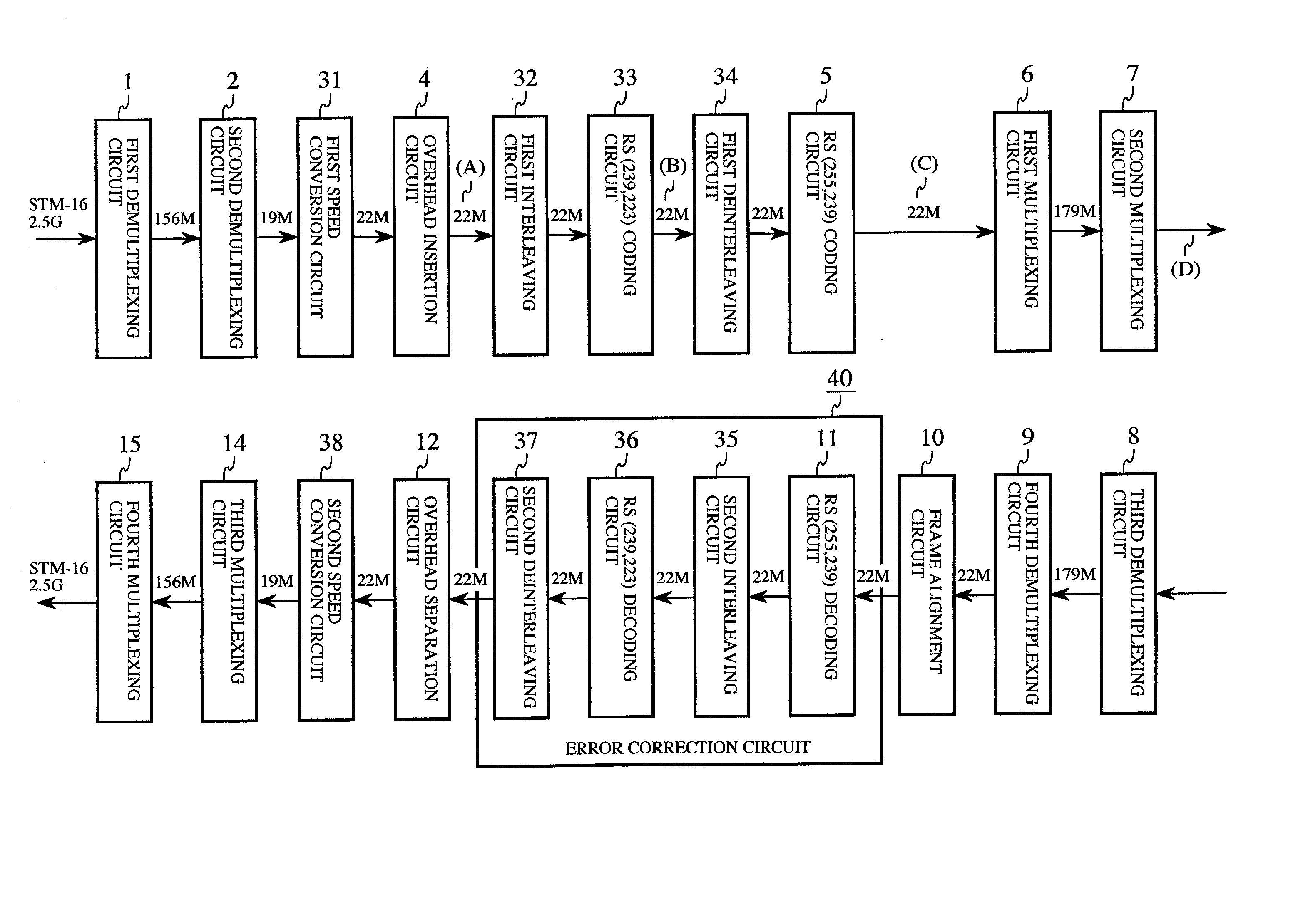
[0068] FIG. 9 is a schematic diagram showing an FEC multiplexer according to the second embodiment of the invention. This FEC multiplexer comprises an error correction circuit (error correction means) 40 connected in a multistage and cascaded manner. The error correction circuit 40 includes: an RS (255, 239) decoding circuit 11; a second interleaving circuit 35; an RS (239, 223) decoding circuit 36; and second interleaving circuit 37.

[0069] Next, an operation will be described.

[0070] In FIG. 9, the error correction circuit 40 is connected in the multistage and cascaded manner in the FEC demultiplexing circuit 26. According to the second embodiment, the operations of bit error correction are sequentially repeated for two kinds of error correction codes. Thus, the error correction capability can be further enhanced, and it is possible to build a long-haul and large-capacity optical transmission system without changing the configuration of the FEC frame or cha...

third embodiment

[0071] (Third Embodiment)

[0072] FIG. 10 is a view illustrating an FEC frame structuring method according to a third embodiment of the invention. According to this method, with the number k (k=4) of FEC frames set as one cycle, interleaving is executed by a number of n / m (=128 / 8=16) times by shifting the information of each FEC frame to be interleaved by 16 bits, and interleaving is carried out by totally 1 times (l is larger by k times than n / m: 16.times.4=64).

[0073] Next, an operation will be described.

[0074] In the foregoing first embodiment, the number of interleaving times l between the two kinds of codes was l=16. However, by setting the number of interleaving times l to be a natural number multiple, e.g., l=32, 48, 64, . . . , it is possible to further enhance the error correction capability while maintaining constant the increase rate of a transmission speed. FIG. 10 shows a case of four FEC frames set as one cycle. In this case, interleaving is carried out by 16 times by shi...


PUM


Abstract

In an FEC frame structuring method, and an FEC multiplexer, the order of information is changed by a first interleaving circuit 32, a first error correction code is generated by an RS (239, 223) coding circuit 33, the order is rechanged to an original order by a first deinterleaving circuit 34, and a second error correction code is generated by an RS (255, 239) coding means 5. The second error correction code is decoded by an RS (255, 239) decoding circuit 11 to correct an error of information, the order of information is changed by a second interleaving circuit 35, the first error correction code is decoded by an RS (239, 223) decoding circuit 36 to correct a residual error of information, and the order is rechanged to an original order by a second interleaving circuit 37.

Description

[0001] This application is the national phase under 35 U.S.C. .sctn.371 of PCT International Application No. PCT / JP00 / 08635 which has an International filing date of Dec. 6, 2000, which designated the United States of America and was not published in English.BACKGROUND OF THE INVENTION[0002] 1. Technical Field[0003] This invention relates to an FEC structuring method and an FEC multiplexer, designed to realize long-haul and large-capacity transmission by correcting a bit error caused by the degradation of optical SNR based on forward error correction (FEC) in an optical transmission system.[0004] 2. Background Art[0005] FIG. 1 is a schematic diagram showing a conventional FEC multiplexer, for example one presented in accordance with ITU-T Recommendation G.975. In the drawing, a reference numeral 1 denotes a first demultiplexing circuit for demultiplexing 2.5 Gbit / s STM-16 data into 16 parallel 156 Mbit / s data; and 2 a second demultiplexer for demultiplexing the 16 parallel 156 Mbit / ...

Claims


Application Information

Patent Timeline
IPC IPC(8): H03M13/15H03M13/27H03M13/29H04J3/00H04L1/00
CPCH03M13/15H03M13/1515H03M13/2721H03M13/2921H03M13/6561
Inventor KUBO, KAZUOYOSHIDA, HIDEOICHIBANGASE, HIROSHITAGA, HIDENORISHIBANO, EIICHIYASUDA, TADAMI
Owner MITSUBISHI ELECTRIC CORP
Why Eureka
Try Eureka