End of valve motion detection for a spool control valve

a technology of spool control valve and end of valve motion, which is applied in the direction of electrical control, instruments, galvano-magnetic hall-effect devices, etc., can solve the problem of difficult to determine exactly when this steep slope occurs

Inactive Publication Date: 2002-09-19
VITESCO TECH USA LLC
View PDF5 Cites 28 Cited by
  • Summary
  • Abstract
  • Description
  • Claims
  • Application Information

AI Technical Summary

Benefits of technology

0010] The present invention therefore provides a method of reliably determining when a fuel injector spool control valve reaches the end of motion.

Problems solved by technology

However, determining exactly when this steep slope occurs is rather difficult when so examining the back emf signal directly considering the extremely small timing envelope of an injection event window and the constant slope change of the signal.

Method used


Image

  • End of valve motion detection for a spool control valve
  • End of valve motion detection for a spool control valve
  • End of valve motion detection for a spool control valve

Examples


Embodiment Construction

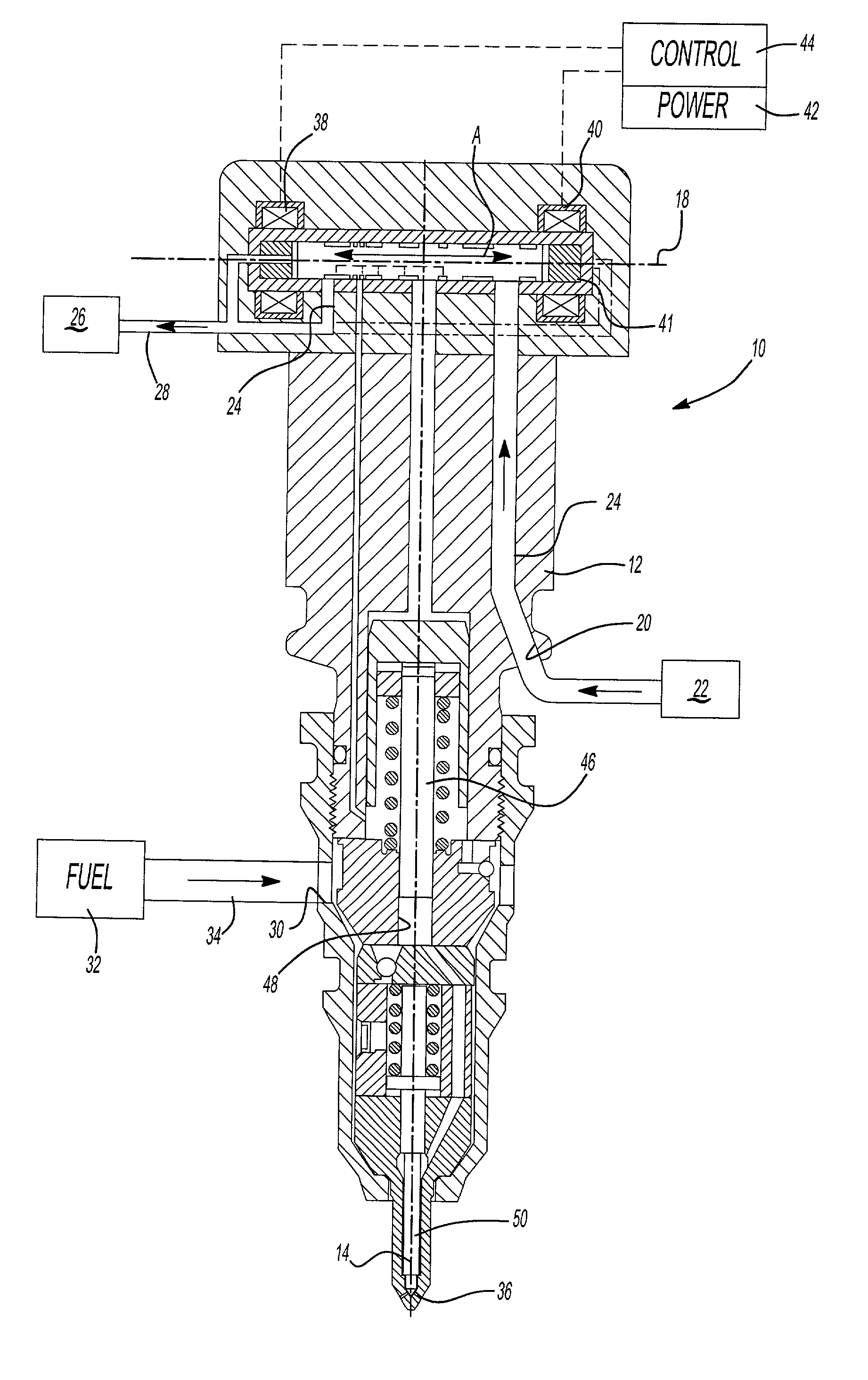
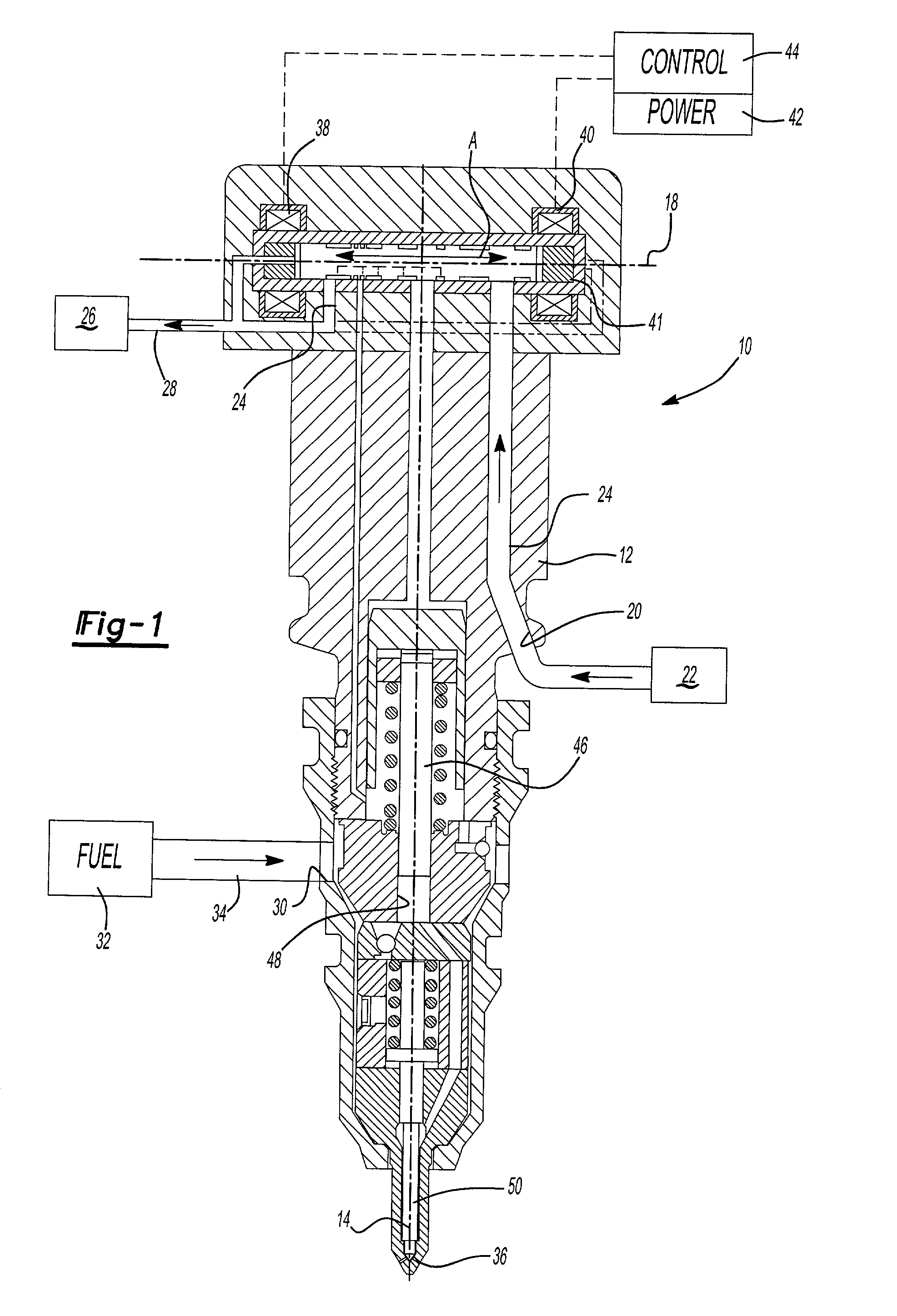
[0015] FIG. 1 illustrates a general perspective view of a fuel injector system 10. The fuel injector includes an injector body 12 which defines an injector axis 14. An electrically controlled spool valve 16 is movable (as schematically illustrated by arrow A) within the injector body 12 along a spool axis 18 defined substantially perpendicular to the injector axis 14. The injector body 12 defines an actuation fluid inlet 20 which communicates with a high pressure actuation fluid source 22 via an actuation fluid supply passage 24. An actuation fluid drain 24 communicates with a low pressure return reservoir 26 via a drain passage 28. Injector body 12 also defines a fuel inlet 30 which communicates with fuel source 32 through a fuel supply passage 34 such that fuel from the fuel source 32 is directed through a nozzle outlet 36 that is preferably appropriately positioned within the combustion space of an internal combustion engine.

[0016] A first and second opposed electric coil 38, 40 ...


PUM


Abstract

A fuel injector system 10 calculates a first derivative filtered signal and a second derivative filtered signal from an unpowered spool valve coil signal. When the spool valve 16 reaches the end of travel, either open or closed position, a flat slope f is generated on the falling edge of the bell shaped signal. The second derivative provides a readily apparent determination of when the steep slope occurs. A comparator 62 thereby need only determine when the second derivative is zero to identify that the spool valve has reached the end of travel.

Description

[0001] The present application claims priority to U.S. Provisional Patent Application Serial No. 60 / 276220, filed Mar. 15, 2001 and U.S. Provisional Patent Application Serial No. 60 / 278223, filed Mar. 23, 2001.BACKGROUND OF THE INVENTION[0002] The present invention relates to a fuel injector system, and more particularly to a method of determining the end of motion of a fuel injector spool control valve.[0003] Fuel injectors typically use a high pressure fluid acting on a relatively large area intensifier piston to compress fuel under a smaller area plunger. When fuel pressure is raised above a valve opening pressure, a needle check valve lifts to open the nozzle outlet, and fuel sprays into the combustion space within an engine.[0004] To accurately control the timing of each injection event, the fuel injectors commonly include a solenoid actuated spool valve that opens and closes the fuel injector to the high pressure actuation fluid. The spool valve is essentially an armature mova...

Claims


Application Information

Patent Timeline
Patent Type & Authority Applications(United States)
IPC IPC(8): F02M51/00F02D41/20F02M47/00F16K31/06
CPCF02D41/20F02D2041/2055F02D2041/2079Y10T137/794
Inventor MCCOY, JOHN CURTISMCCOY, MARY B.HILTUNEN, LARRYMAKAR, SIMONCOBAS-ASENSIO, RAFAELMUCHA, JASONZHANG, CHANGHONG
Owner VITESCO TECH USA LLC
Why Eureka
Try Eureka