Evaluating method for NOx eliminating catalyst, an evaluating apparatus therefor, and an efficiency controlling method therefor

a technology of nox eliminating catalyst and evaluating method, which is applied in the direction of electrical control, exhaust treatment electric control, separation process, etc., can solve the problems of prior art not being able to accurately control the amount of hc, and not being able to evaluate the catalyst correctly, so as to achieve efficiency and a deterioration degree

Inactive Publication Date: 2002-09-19
HITACHI LTD
View PDF0 Cites 5 Cited by
  • Summary
  • Abstract
  • Description
  • Claims
  • Application Information

AI Technical Summary

Benefits of technology

[0019] In the above evaluating apparatus, oxygen concentration in exhaust gas at downstream of the NO.sub.x eliminating catalyst increases by reducing effect of the NO.sub.x eliminating catalyst. Therefore, efficiency and a deterioration degree of the NO.sub.x eliminating catalyst can be estimated by comparing physical parameters of specified gas components at upstream side and that at downstream side of the NO.sub.x eliminating catalyst.

Problems solved by technology

However, there has been a problem that the prior art described above are unable to evaluate the catalyst correctly because they use a travelling distance as a parameter for evaluating the catalyst indirectly.
Furthermore, regarding to the prior art controlling the amount of HC, there has been a problem that the prior art can not control the amount of HC correctly because it controls the amount of HC irrelevant to the evaluating result of the catalyst deterioration.

Method used


Image

  • Evaluating method for NOx eliminating catalyst, an evaluating apparatus therefor, and an efficiency controlling method therefor
  • Evaluating method for NOx eliminating catalyst, an evaluating apparatus therefor, and an efficiency controlling method therefor
  • Evaluating method for NOx eliminating catalyst, an evaluating apparatus therefor, and an efficiency controlling method therefor

Examples


embodiment 1

[0055] Embodiment 1

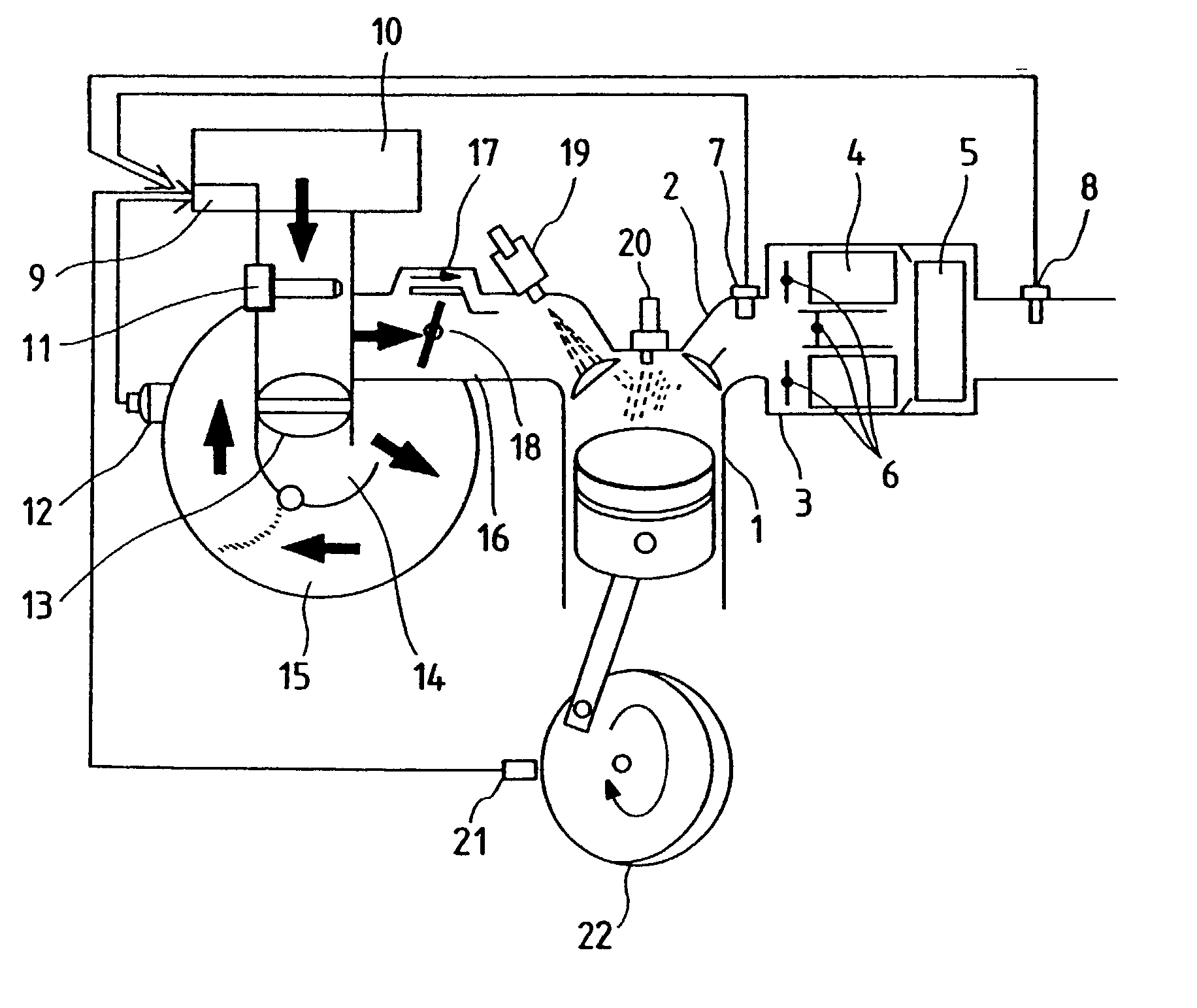
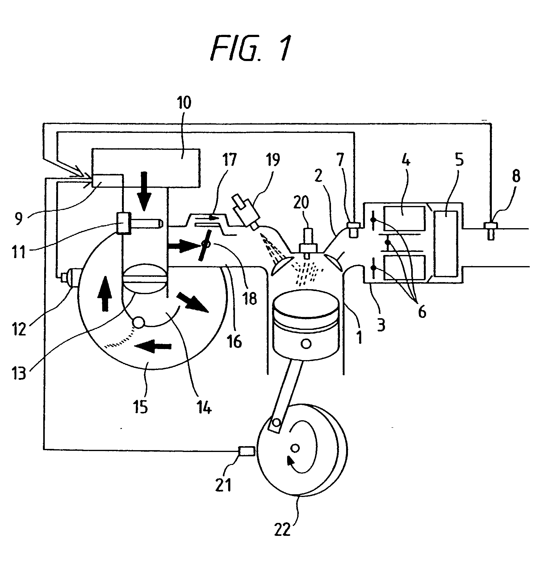
[0056] A simplified diagrammatic view showing a total system of an embodiment of the present invention is illustrated in FIG. 1.

[0057] A catalyst 3 is connected to an exhaust gas pipe 2 of an engine 1. In the catalyst 3, lean NO.sub.x catalysts 4 for eliminating NO.sub.x under a lean air-fuel ratio condition, and a three way catalyst or an oxide catalyst 5 for eliminating NO.sub.x, CO, and HC under a theoretical air-fuel ratio condition. The catalyst 3 is composed in a manner so as to switch the above two kinds of catalysts by switching valves 6 depending on an operating condition of the engine. As for the lean NO.sub.x catalyst, a copper-zeolite catalyst containing metals, for example, can be used. However, the above exemplified catalyst generally has such a characteristics that the catalyst deteriorates itself under a high temperature or a rich air-fuel ratio condition. Therefore, bypassing the lean NO.sub.x catalyst are preferable in some cases, for example, wh...

embodiment 2

[0068] Embodiment 2

[0069] Further, another embodiment of the present invention is shown in FIG. 11. In the present embodiment, a prefixed catalyst 53 and a postfixed catalyst 54 in a downstream side were arranged in series, and three sensors, 50, 51, 52 were installed. Efficiency and a deteriorating degree of the prefixed catalyst 53 are determined by the method explained in the previous embodiment using the sensors 5, 51. Efficiency and a deteriorating degree of the postfixed catalyst 54 are determined by the method explained in the previous embodiment using the sensors 51, 52, or sensors, 50, 52. In accordance with the above described arrangement, deterioration diagnosis of a complex catalyst system becomes possible. As for the catalyst, a NO.sub.x reducing catalyst is used for the prefixed catalyst 53 and a three way catalyst or an oxidizing catalyst is used for the postfixed catalyst 54. In this case, a deteriorating degree of the NO.sub.x reducing catalyst 53 is determined by c...

embodiment 3

[0073] Embodiment 3

[0074] Furthermore, another embodiment of the present invention is illustrated in FIG. 13. In this case, a plurality of catalysts are arranged in parallel. Catalysts 55, 56 are arranged in parallel, and a catalyst to which exhaust gas is flowed is selectively alterable depending on its operating condition by switching valves 57A, 57B driven by an actuator 58 which is operated by loads or electric power. For instance, when the switching valve 57A is open so as to flow the exhaust gas to the catalyst 56, the switching valve 57B is close so as not to flow the exhaust gas to the catalyst 55. In this case, efficiency or deterioration of the catalyst 56 must be judged based on signals from the sensors 58, 59 when the operating condition is such that the catalyst 56 must work. When the switching valves 57A, 57B are rotated so as to flow the exhaust gas to the catalyst 55, the exhaust gas flow to the catalyst 56 is stopped. In this case, efficiency or deterioration of the...


PUM

PropertyMeasurementUnit
physical parametersaaaaaaaaaa
concentrationaaaaaaaaaa
ion conductiveaaaaaaaaaa

Abstract

In order to prevent a catalyst for an internal combustion engine from decreasing efficiency by deterioration after long time use of the catalyst, the decreased efficiency of the catalyst is determined, and the internal engine is controlled based on results of the determination so as to maintain high efficiency of the catalyst. The catalyst is installed in an exhaust pipe of the engine. Sensors for detecting conditions of exhaust gas both at upstream side and downstream side of the catalyst are provided, respectively. As for the sensor, for example, an oxygen sensor of which output varies stepwise at lambd=1, or a sensor of which output varies in proportion to air-fuel ratio can be used. Detected values of the sensors are taken into a control unit, eliminating efficiency and deteriorating degree of the catalyst are estimated by comparison of the detected values, and the engine is controlled so that the eliminating efficiency becomes maximum. In accordance with the present invention, a preferable exhaust gas cleaning characteristics of the catalyst can be maintained because the decreased efficiency of the catalyst is determined exactly and the engine is controlled so as to prevent the catalyst from decreasing efficiency.

Description

[0001] (1) Field of the Invention[0002] The present invention relates to an evaluating method for NO.sub.x eliminating catalyst provided in an exhaust gas system of internal combustion engines, an evaluating apparatus therefor, and an efficiency controlling method therefor. The above described NO.sub.x eliminating catalyst means essentially a catalyst for eliminating NO.sub.x components in exhaust gas for cleaning the exhaust gas in the exhaust gas system of the internal combustion engine.[0003] (2) Description of the Prior Art[0004] As for a method for estimating efficiency decrease and deterioration of NO.sub.x eliminating catalyst, a method has been proposed in JP-A-4-265414 (1992), for example, wherein, taking a travelling distance of an automobile as a parameter, efficiency of NO.sub.x eliminating catalyst in the automobile is deemed to be sufficiently deteriorated when the travelling distance exceeds a designated value.[0005] Further, a method for increasing an amount of hydro...

Claims


Application Information

Patent Timeline
Patent Type & Authority Applications(United States)
IPC IPC(8): B01D53/30B01D53/86B01D53/94F01N3/20F01N3/24F01N11/00F02D41/02
CPCB01D53/8696B01D53/9495F01N11/007F01N2550/02F02D41/0235Y02T10/47Y02T10/22Y10T436/177692Y10T436/20Y10T436/21Y10T436/206664Y10T436/208339Y02T10/12Y02T10/40
Inventor OHSUGA, MINORUFUJIEDA, MAMORUKURIHARA, NOBUO
Owner HITACHI LTD
Why Eureka
Try Eureka