
Web transporting mechanism of printing apparatus

a transport mechanism and printing apparatus technology, applied in electrographic processes, manufacturing tools, instruments, etc., can solve the problems of transporting blurring, deteriorating printing quality, fluctuating web transporting speed, etc., to reduce transporting blurring, enhance printing quality, and high printing quality

Active Publication Date: 2008-11-18
RICOH KK
View PDF3 Cites 0 Cited by
  • Summary
  • Abstract
  • Description
  • Claims
  • Application Information

AI Technical Summary

Benefits of technology

The patent text describes a problem in printing apparatuses where the speed of transporting the web in the fixing section is not perfectly synchronized with the speed of transporting the web in the transporting section, resulting in transporting blurring and quality of printing being affected. To solve this problem, the patent proposes a web transporting mechanism with a movable buffer that absorbs fluctuations in the web length and a brake member to suppress the motion of the movable buffer. This mechanism reduces the shock experienced when the movable buffer comes into contact with the web, resulting in improved printing quality and stability of the continuous transporting of the web.

Problems solved by technology

However, when the spring constant of the twist coil spring is set at the high value, a transporting blurring is caused immediately after the start of transporting operation, and quality of printing is deteriorated as described as follows.
At this time, the web slips on the web transporting roller by the shock generated at this time, and the web transporting speed fluctuates and transporting blurring is caused.
Therefore, the transporting blurring is deteriorated, and the quality of printing is deteriorated immediately after the start of transporting the web.
Therefore, it has become difficult to reduce a difference between the speed of transporting the web in the transporting section and the speed of transporting the web in the fixing section.
As a result, the degree of the transporting blurring is deteriorated by the shock caused when the movable buffer comes into contact with the web again, and the quality of printing is deteriorated immediately after the transporting operation has started.

Method used


Image

  • Web transporting mechanism of printing apparatus
  • Web transporting mechanism of printing apparatus
  • Web transporting mechanism of printing apparatus

Examples


embodiment 1

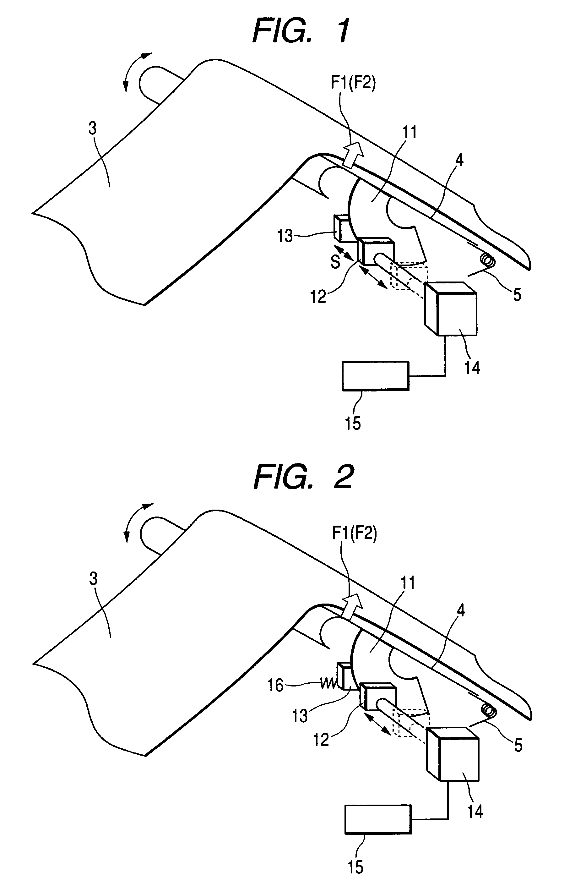
[0019]Embodiment 1 of the buffer mechanism section of the present invention will be explained below referring to FIG. 1.

[0020]In FIG. 1, reference numeral 3 is a web. In many cases, the web 3 is usually made of paper used for a printing apparatus. However, the web 3 is not necessarily limited to paper. In some cases, a plastic film is used as the web 3.

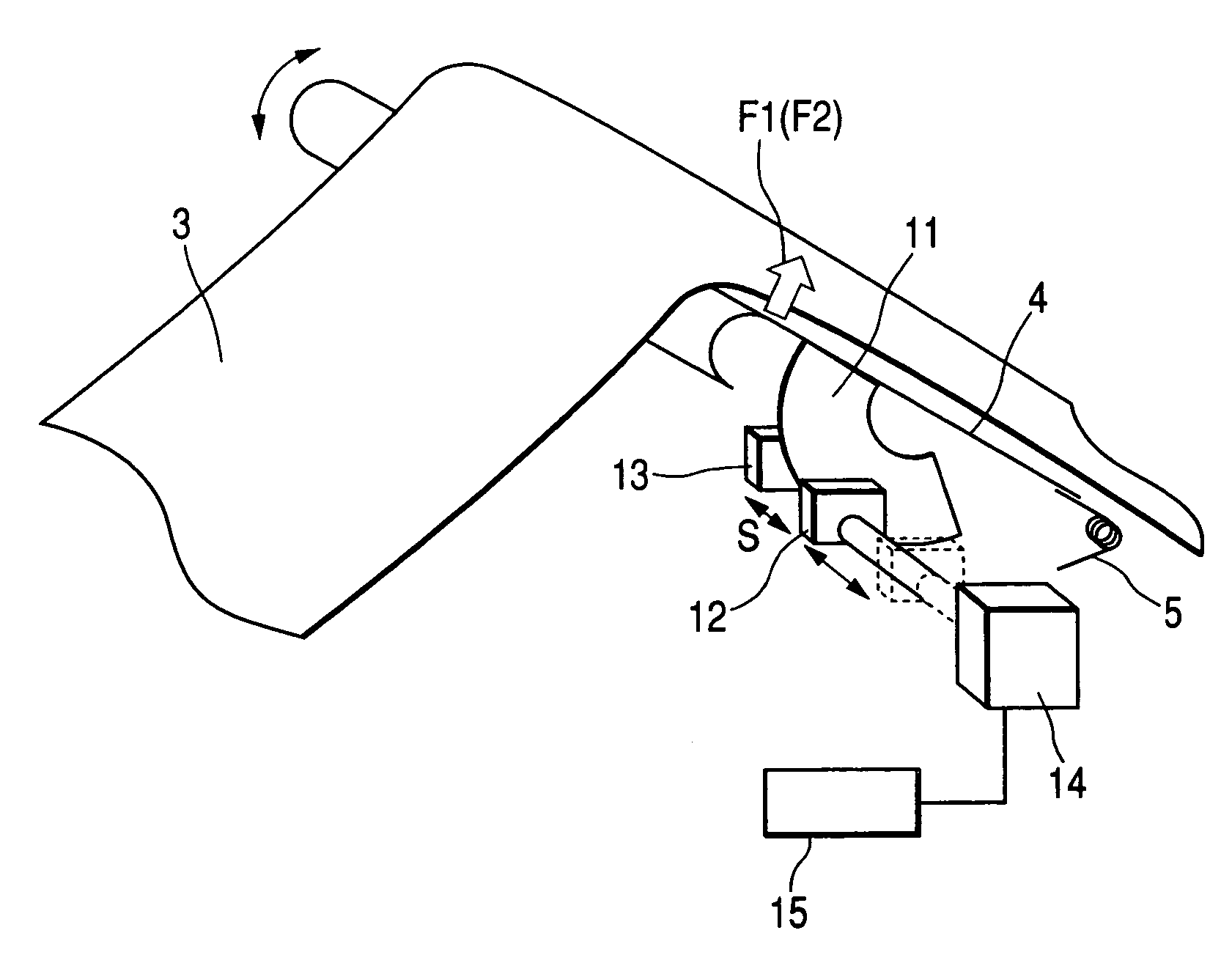
[0021]The brake plate 11 is provided in the movable buffer 4 located between the transporting section 1 and the fixing section 2. The support member 13 for supporting a pushing force of the brake member 12 is arranged at a position opposed to the brake member 12 while the brake plate 11 is being interposed between the brake member 12 and the support member 13. Due to this structure, the brake plate 11 is given a frictional force. Therefore, the original reaction force F1 given to the movable buffer 4 by the twist coil spring 5 is canceled by the frictional load, so that the reaction force F1 can be reduced. The brake member 12 is arra...

embodiment 2

[0024]Embodiment 2 is shown in FIG. 2. In this embodiment, the spring 16 is arranged at the rear of the support member 13 of Embodiment 1. In the case of the brake mechanism of the present invention, as the brake mechanism is frequently used, the contact faces of the brake plate 11, the brake member 12 and the support member 13 are abraded and the pushing force (frictional load) is decreased. Accordingly, there is a possibility that the reaction force F2 of the movable buffer immediately after the start of transporting the web is changed with time. However, when the pushing force is further given by the spring 16 and the spring constant of the spring 16 is set at a value as low as possible, it is possible to reduce a change in the pushing force (frictional load) relying on the pushing stroke which has changed by the abrasion of the contact faces described above. In this embodiment, the spring 16 is arranged on the support member 13 side. However, the spring 16 may be attached to the...


PUM


Abstract

A web transporting mechanism of a printing apparatus has a buffer mechanism section for absorbing a fluctuation of the web length from a transporting section to a fixing section generated by a difference between a speed of transporting a web in the transporting section and a speed of transporting a web in the fixing section. The web transporting mechanism includes at least one brake member suppressing a motion of a movable buffer. The brake member has a drive means.

Description

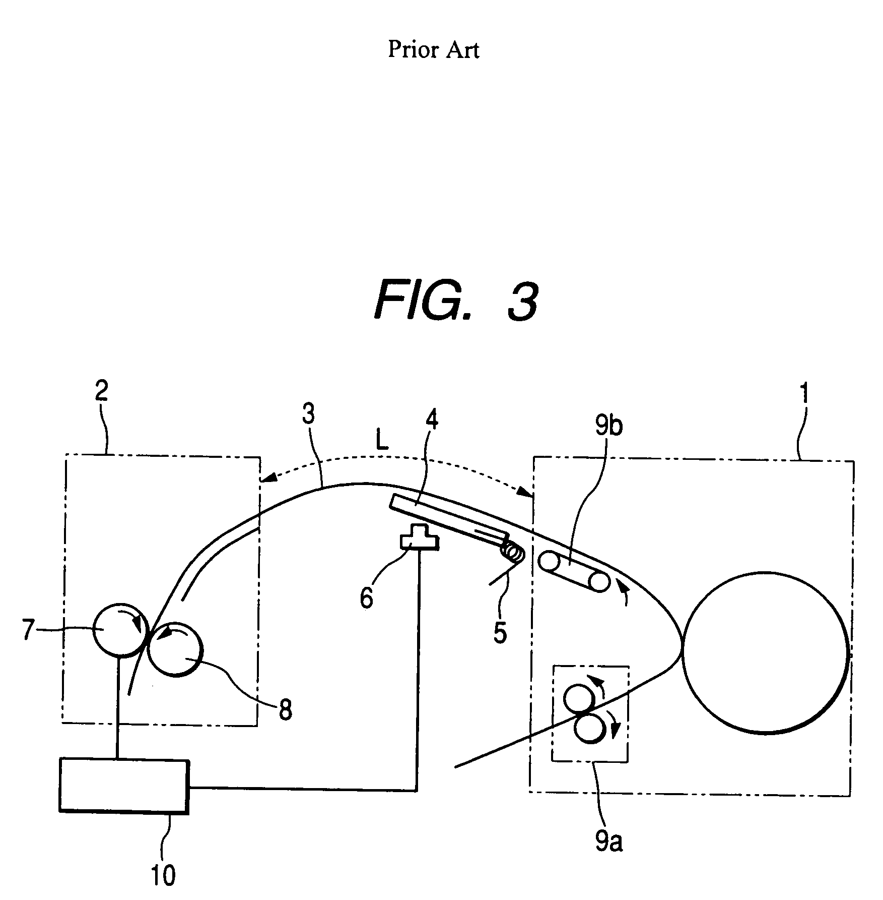
BACKGROUND OF THE INVENTION[0001]1. Field of the Invention[0002]The present invention relates to a web transporting mechanism of a printing apparatus for forming an image on a web continuously transported. More particularly, relates to the web transporting mechanism of the printing apparatus having a buffer mechanism for absorbing a fluctuation of a web length between a transporting section and a fixing section.[0003]2. Description of the Related Art[0004]In a printing apparatus for forming an image on a continuous web, the web is transported in such a manner that a pin member of a tractor mechanism mounted on the printing apparatus is engaged in a sprocket hole of the web of paper and the web is transported when the tractor mechanism is driven. In the case where the web having the sprocket holes is used, it is necessary to cut off both end portions of the web, in which the sprocket holes are formed, after the completion of printing. Therefore, a printing apparatus has been put into...

Claims


Application Information

Patent Timeline
Patent Type & Authority Patents(United States)
IPC IPC(8): B65H20/00G03G15/00G03G15/20B23Q15/00B65H23/10B65H23/188G03G15/16
CPCB65H23/10G03G2215/00455
Inventor OHMURA, YUJIONOSE, TSUKASATERAKADO, TAKESHIIWANAGA, HIDENORI
Owner RICOH KK
Learn More