Landing craft with fixed and retractable azimuthing drives

a technology of azimuthing drive and landing craft, which is applied in the field of marine vessels, can solve the problems of limited maneuverability of marine vessels, limited cargo capacity of larger marine vessels, and difficulty in transferring, and achieves the effect of high maneuverability of the disclosed marine vessel

Inactive Publication Date: 2002-09-26
KVAERNER MASA MARINE
View PDF0 Cites 21 Cited by
  • Summary
  • Abstract
  • Description
  • Claims
  • Application Information

AI Technical Summary

Benefits of technology

0015] The marine vessel described herein has the ability to travel in multiple directions, particularly stern forward, during landing operations on a beach or other unimproved water / land interface. The high maneuverability of the disclosed marine vessel is accomplished through the use of conventional steerable or azimuthing drives mounted below the waterline on the bow and stern portions of the craft.

Problems solved by technology

Without docking facilities, such transfers are difficult to accomplish.
Unfortunately, such craft were limited to transporting a relatively small group of men, one or two vehicles, or an inadequate amount of cargo, due to their limited size and cargo weight capacity.
Larger marine vessels were limited for such operations due to their inability to effectively and safely "beach" themselves to unload cargo and then return to normal seakeeping operations.
An obvious disadvantage of using one ramp is that vehicles must be "rolled-on" in reverse, such that they can be driven off the vessel in a forward orientation so that they can be immediately used.
When loading / unloading ramps are provided at both the bow and the stern of the ship, such vessel still suffer from several disadvantages, particularly if used during beaching operations.
However, the use of ramps and other offloading systems located on the ship's bow affected the seakeeping ability of the ship as design compromises must be made to the hull design which affect the ability to sail through the water and break waves.
Furthermore, due to the compromised designs of such hulls, the bow ramps would suffer damage from the force of wave impacts, beaching and general sailing operations.
Prior art landing craft are also destabilized by the surf slamming into the flat stern of the ship when beached.
Operation of the propulsion system in this manner is inefficient and taxing on the mechanical systems.
This is difficult in rough surf and can result in loss of vessels during combat operations.
However, there is no discussion in Veronesi et al. of utilizing the disclosed thrusters in combination with a vessel configuration which is appropriate for both seagoing and beaching operations.
While incorporating conventionally known z-axis drives to increase maneuverability , the disclosure of Gulling, et al. does not contribute to the problems associated with prior art landing craft.
Again, while the use of steerable drives is discussed, the apparatus and method of Arpiainen does not disclose how such drives, or the hull configuration of the ship, can be used to accomplish beaching operations while maintaining good seakeeping abilities.

Method used


Image

  • Landing craft with fixed and retractable azimuthing drives
  • Landing craft with fixed and retractable azimuthing drives
  • Landing craft with fixed and retractable azimuthing drives

Examples


Embodiment Construction

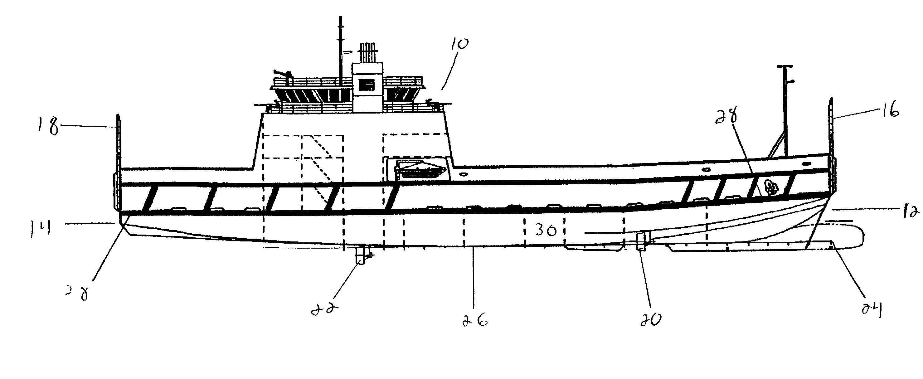
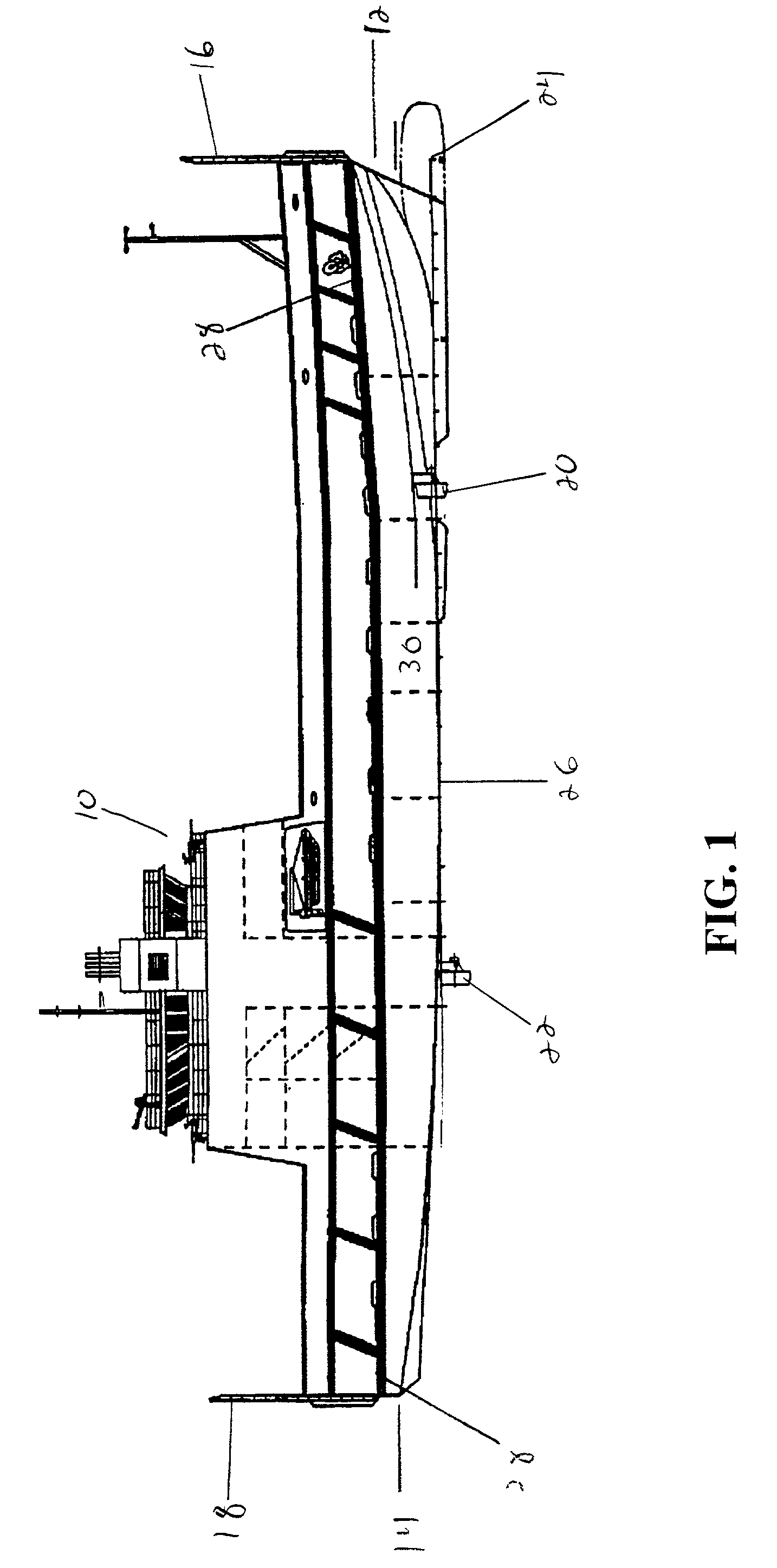
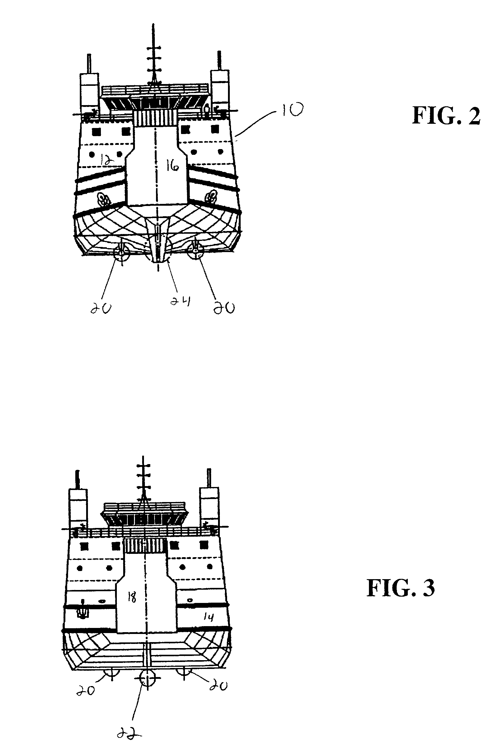
[0029] Referring to FIG. 1, vessel 10 generally contains a boat hull 30 having a bow portion 12, a stem portion 14 and a keel 26. Located at the bow 12 is a bow ramp 16. The bow ramp 16 is generally used to load vehicles or other cargo onto the vessel 10. Located at the stem 14 is a stem ramp 18 that is generally used to offload vehicles or other cargo, particularly during beaching operations. Below the waterline of the vessel 10 are two sets of azimuthing or steerable thruster drives 20 and 22. At least one drive 20 is located on the bow portion 12 of the vessel. Similarly, at least one drive 22 is located on the stem portion 14 of the vessel. In the preferred embodiment of the invention, vessel 10 contains two bow thrusters 20 and two stern thrusters 22. However, as shown in FIGS. 2 and 3, one stem thruster 22 may be used in combination with two bow thrusters 20.

[0030] Referring to FIGS. 1 and 2, the bow portion 12 of the vessel 10 incorporates, to the extent possible, characteris...


PUM


Abstract

A marine vessel used for loading and offloading vehicles and cargo that has both excellent seakeeping and beaching properties. The vessel is provided with azimuthing or steerable thrusters below the waterline at the bow and stern of the ship, with the stern end thrusters being retractable into the hull during beaching operations. Because the vessel is beached "stern first" the bow may be designed with better wave breaking and seakeeping features than are on prior landing craft designs.

Description

[0001] 1. Field of Invention[0002] This invention relates to a marine vessel, and more particularly, to a landing craft that uses fixed and retractable azimuthing drives in combination with an improved bow shape to obtain both excellent seakeeping and beaching abilities.[0003] 2. Description of Prior Art[0004] Throughout the history of modern military operations, there has been a requirement to transfer men and materials from ships to a beachhead. Without docking facilities, such transfers are difficult to accomplish. In the twentieth century, particularly during the Second World War, specialized landing craft were developed to facilitate such transfers. Unfortunately, such craft were limited to transporting a relatively small group of men, one or two vehicles, or an inadequate amount of cargo, due to their limited size and cargo weight capacity. Larger marine vessels were limited for such operations due to their inability to effectively and safely "beach" themselves to unload cargo...

Claims


Application Information

Patent Timeline
Patent Type & Authority Applications(United States)
IPC IPC(8): B63B27/00B63B27/14B63B35/54
CPCB63B27/00B63B27/143B63B35/54B63B2035/001B63H2025/425
Inventor ARMOUR, ROBERT
Owner KVAERNER MASA MARINE
Why Eureka
Try Eureka