Pedometer navigator system

Inactive Publication Date: 2002-10-03
APPLANIX
View PDF5 Cites 73 Cited by
  • Summary
  • Abstract
  • Description
  • Claims
  • Application Information

AI Technical Summary

Benefits of technology

0044] The navigation frame to be used by the preferred embodiment will be the geographic or NED frame for simplicity but without loss of generality. The Euler angles measured by an EAMS with respect to the geographic frame are called roll, pitch and true heading. It should be understood that there is no loss

Problems solved by technology

Running introduces errors as both feet break contact with the

Method used


Image

  • Pedometer navigator system
  • Pedometer navigator system
  • Pedometer navigator system

Examples


first embodiment

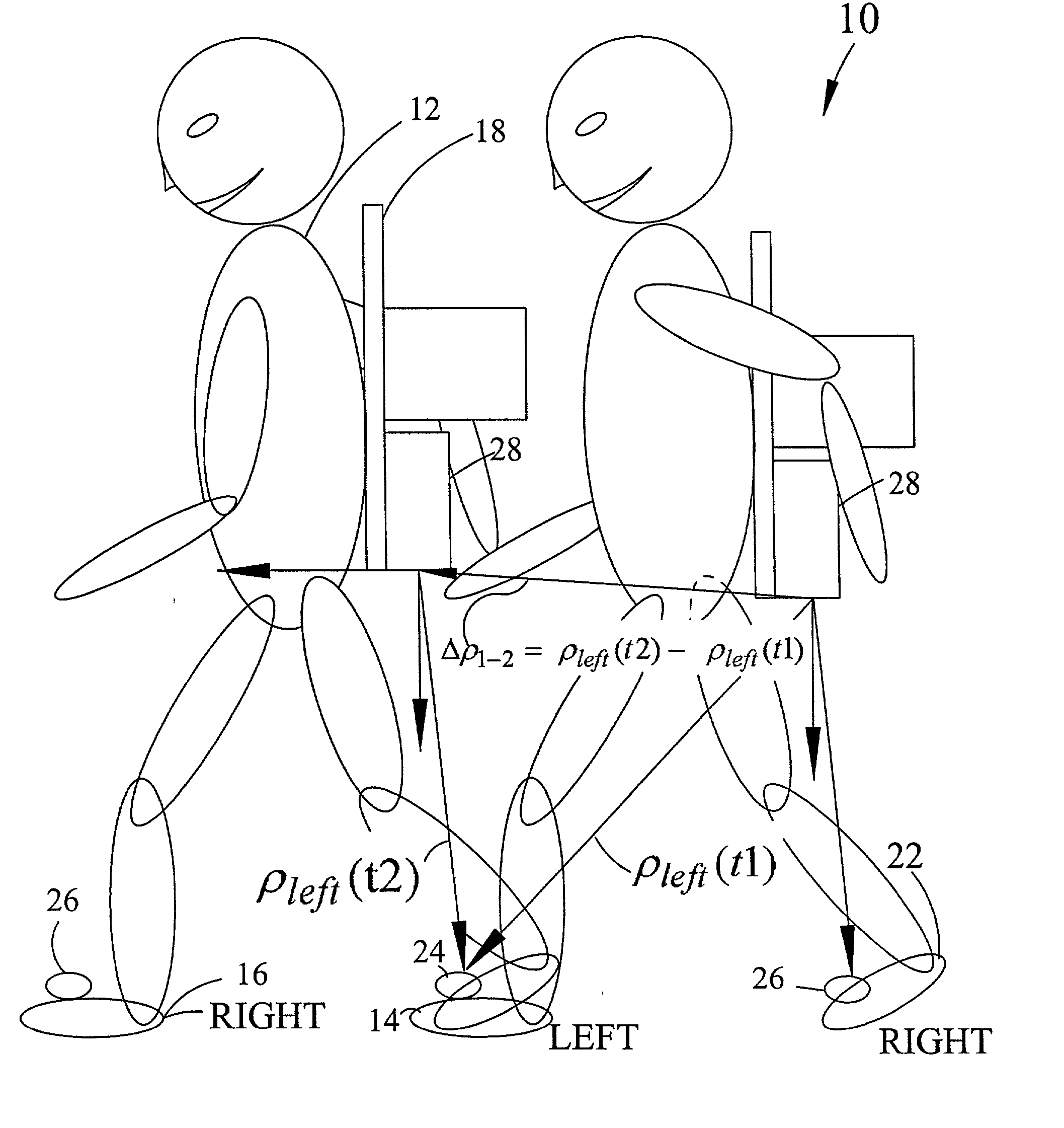
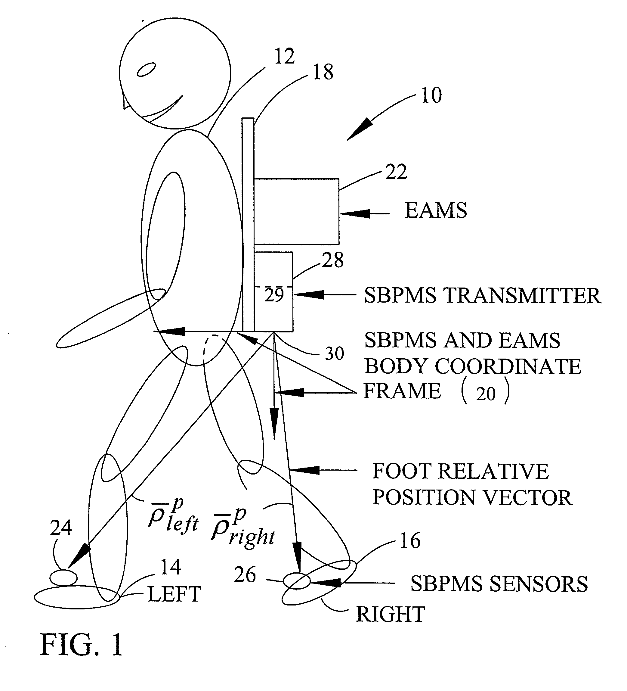
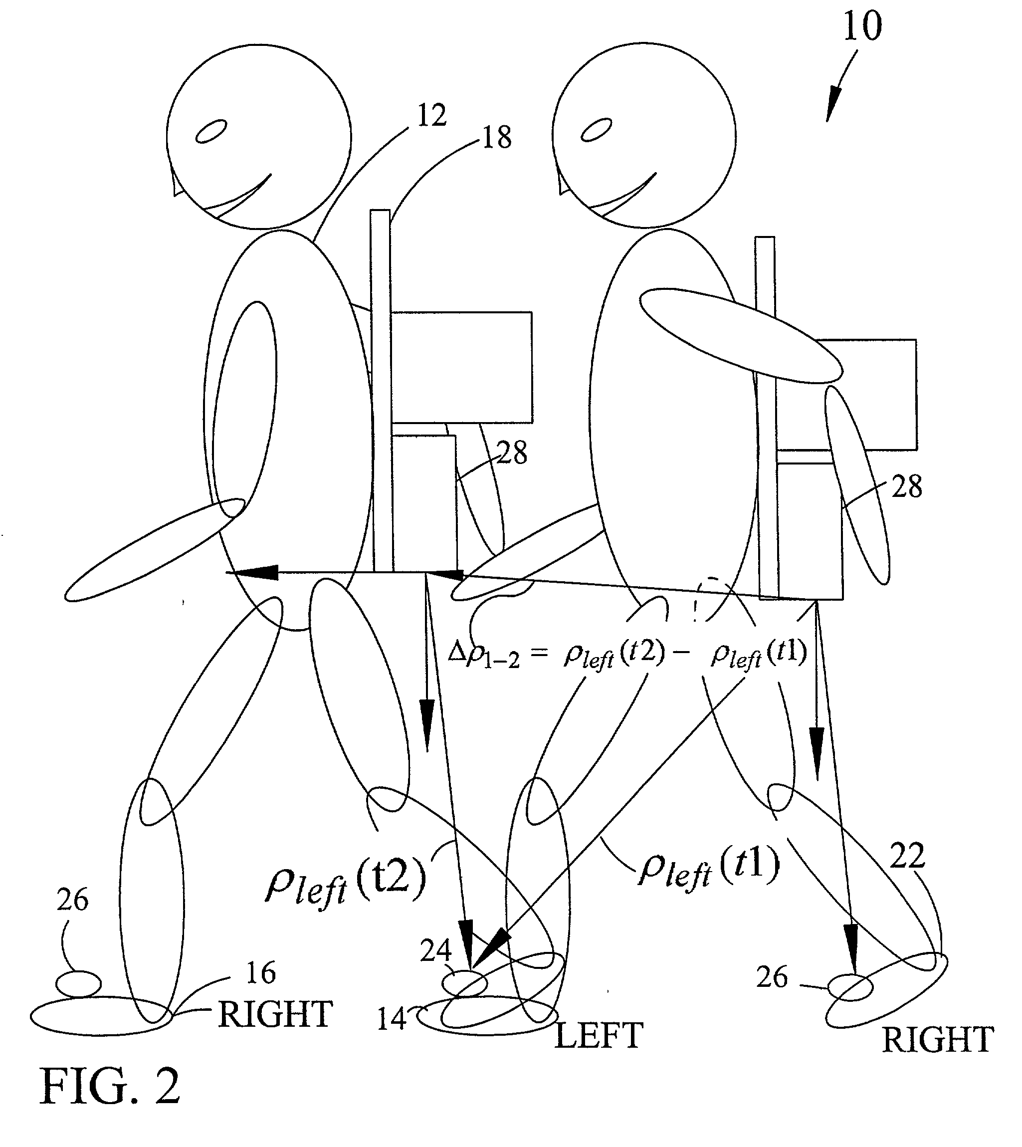
[0047] FIG. 3 shows the PPN, a backpack combination, called the Precise Pedometer Simple Mechanization (PPNSM) 32. The PPNSM 32 uses any EAMS 22 or Attitude and Heading Reference System (AHRS) for Euler angle measurement and an SBPMS 28 for the generation of foot time indexed relative position vector {right arrow over (.rho.)}.sub.left.sup.p and {right arrow over (.rho.)}.sub.right.sup.p shown in FIGS. 1 and 2. The SBPMS is an accurate vector measuring system such as those available from Polhemus Inc. of 40 Hercules Drive, P.O. Box 560, Colchester, Vt. 05446, USA, for foot position vector generation.

[0048] The PPNSM transforms the time-indexed relative position vectors into SBPMS left foot and right foot relative position vectors in the common geographic frame, the g-frame. The PPNSM then uses the SBPMS left foot and right foot relative position vectors to calculate a sequence of SBPMS left relative displacement vectors and right relative displacement vectors in the g-frame each of ...

second embodiment

[0049] FIG. 6 schematically shows the PPN 10, the Precise Pedometer Aided INS (PPAINS) 34 as a backpack combination. The PPAINS 34 combination is the preferred embodiment or best mode for practicing the invention in terms of achievable accuracy and flexibility of use. FIG. 7 is a schematic block diagram of the PAINS combination 34. An Aided Inertial Navigation System (AINS) 36 is available from Applanix, the assignee as well as from a number of other supplier of inertial guidance systems such as the Guidance Systems Division of Litton Systems, Inc. of Woodland Hills, Calif., and an accurate SBPMS 28 system is available from Polhemus Inc. of 40 Hercules Drive, P.O. Box 560, Colchester, Vt. 05446, USA.

[0050] Unlike the SBPMS, the PPAINS 34 does not use the vector information from the SBPMS to calculate an aggregate SBPMS position displacement vector. The PPAINS system uses the computed SBPMS left and right relative displacement vectors from each step as aiding data for the Kalman filt...


PUM


Abstract

A pedometer navigator system is carried by a pedestrian, the pedometer system providing present position data as the pedestrian walks across terrain to be surveyed. The body frame is coupled to the pedestrian. An Euler Angle Measuring Subsystem (EAMS) coupled to a body frame measures and outputs the Euler angles of a fixed coordinate system with respect to an earth fixed navigational coordinate system. A left and right sensor is mounted on the pedestrian's respective left and right foot. An SBPMS (short baseline position measuring subsystem) is coupled to the body frame and has a position measuring coordinate system. The SBPMS measures and provides a respective left vector {right arrow over (rho)}leftp and a right vector {right arrow over (rho)}rightp characterizing the position of the left and right sensors with respect to the position measuring coordinate system origin. A computer and algorithm means responds to the Euler angles of the body frame coordinate system with respect to the earth fixed navigational coordinate system and the left vector and the right vector by determining an interval during which the left or right foot is stationary and for providing a transition vector referenced to the earth fixed navigational coordinate system characterizing the movement of the SBPMS origin during the interval the respective foot is stationary. A navigation algorithm adds each transition vector to the previous present position of the navigation reference system to obtain a next present position of the position measuring subsystem.

Description

[0001] This application is a Continuation-In-Part Application and formalization of Provisional Application serial No. 60 / 226,481 filed Aug. 18, 2000 having a common inventor and assignee.[0002] This invention relates to the field of pedometers and in particular to pedometers using an AINS (aided inertial navigation system).[0003] Simple Pedometer: The simple pedometer is exemplified by a hiker's pedometer. It detects the up-down motion of the pedestrian as he takes a step, sums the number of up-down movements, and then multiplies the sum by an assumed step length. The pedestrian calibrates the pedometer by walking a measured distance and then manually entering that distance into the pedometer. The pedometer in fact maintains a simple step model for the pedestrian, and will need to be recalibrated when a different pedestrian uses the pedometer.[0004] A complex version of a pedometer is taught in U.S. Pat. No. 5,724,265 for a "System AND METHOD FOR MEASURING MOVMENT OF OBJECTS" issued...

Claims


Application Information

Patent Timeline
IPC IPC(8): G01C21/16G01C22/00
CPCG01C22/006G01C21/16G01C21/188
Inventor SCHERZINGER, BRUNO M.
Owner APPLANIX
Why Eureka
Try Eureka