
Data stream filtering apparatus & method

Inactive Publication Date: 2002-10-10
RPX CLEARINGHOUSE
View PDF8 Cites 169 Cited by
  • Summary
  • Abstract
  • Description
  • Claims
  • Application Information

AI Technical Summary

Benefits of technology

[0040] Multiple access networks allow fibre and exchange end equipment to be shared across groups of end customers, resulting in a more cost effective infrastructure. Advantageously the present invention allows the operator to provide very simple, low cost and low power terminations to a GEPON or other point-to-multipoint network, providing a very clear demarcation point between network and customer-side equipment. The complex, and varying functionality of different customer premises equipment can then be treated independently of the GEPON physical network--potentially the customer will purchase his Customer Premises Equipment (CPE) directly, resulting in significant cost savings to the operator.

Problems solved by technology

One significant problem with a GEPON is that all downstream traffic is broadcast and hence visible to all end-nodes, which are likely to be unrelated home or business customers.
A second problem with a GEPON is that, unlike a conventional Ethernet Access system based on point-to-point links, there are multiple customers associated with a single physical port at the headend.
There are however several disadvantages to this approach.
Simple layer 2 bridging of traffic destined for these different CPE devices (e.g. PCs, Set Top Boxes etc) cannot therefore be used, forcing the use of a more complex solution such as layer 3 switching via a router.
This solution is not however suitable for multicast traffic, such as multicast video, which uses a different multicast MAC address.
This however can create significant security problems, as a CPE device such as a PC on one ONU could relatively easily impersonate a device on another ONU and hence steal traffic destined for that ONU.
In any practical system, this mechanism must be automatic and therefore adds further complexity in the ONU.
This is however an expensive solution, and does not fit the commercial and perhaps regulatory requirements of many operators who require a minimal-functionality ONU capable of providing an inexpensive, simple and clear demarcation point at the edge of their network.

Method used


Image

  • Data stream filtering apparatus & method
  • Data stream filtering apparatus & method
  • Data stream filtering apparatus & method

Examples


Embodiment Construction

[0051] This invention relates to the implementation of shared medium or point to multipoint communications systems. An important example of these is a passive optical network (PON).

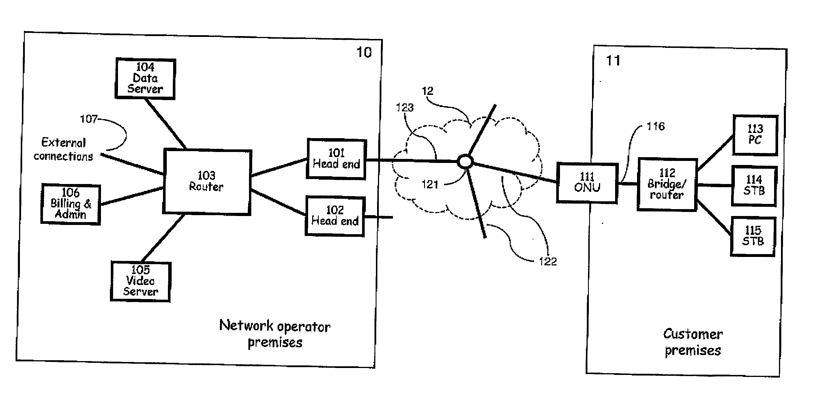
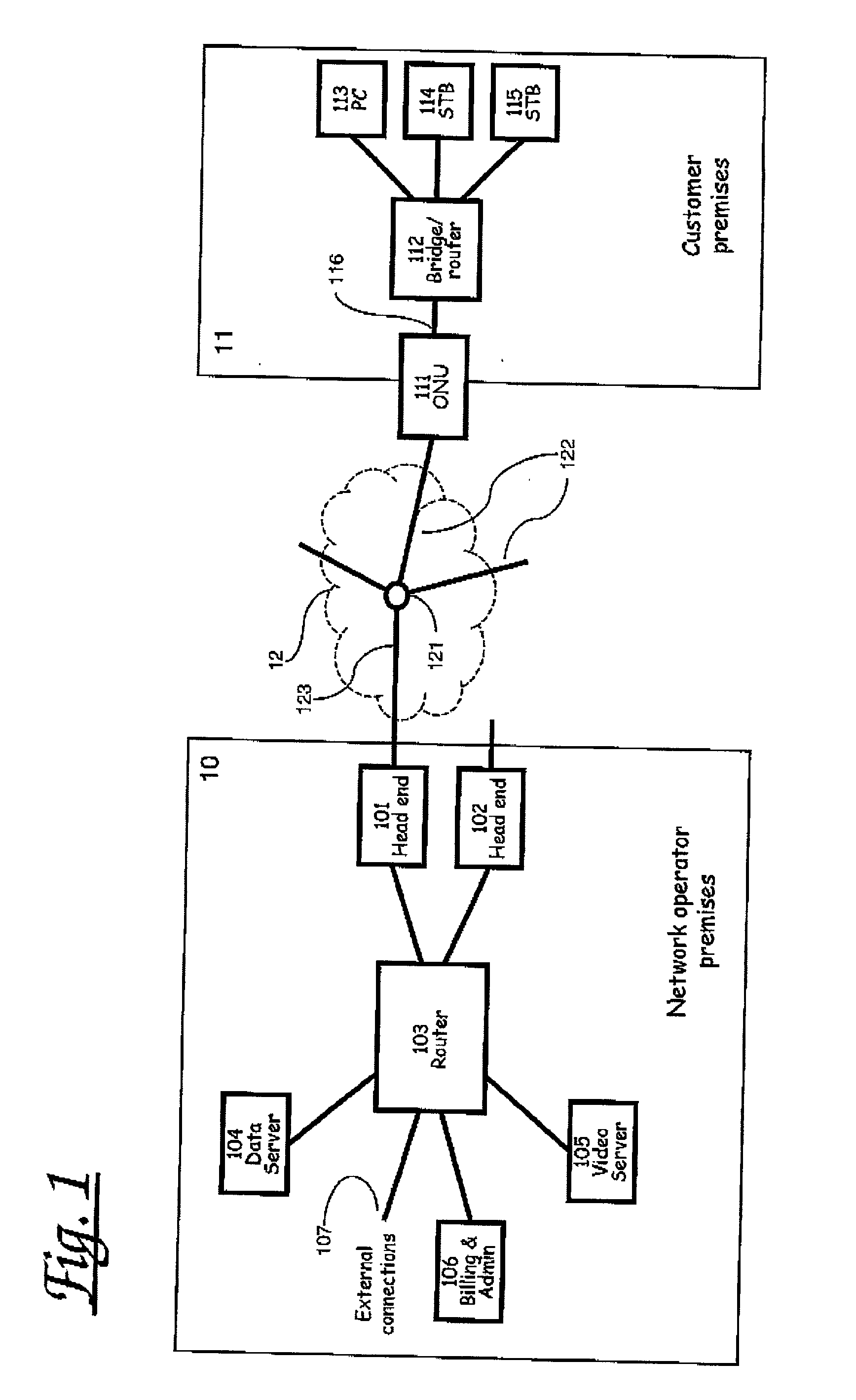
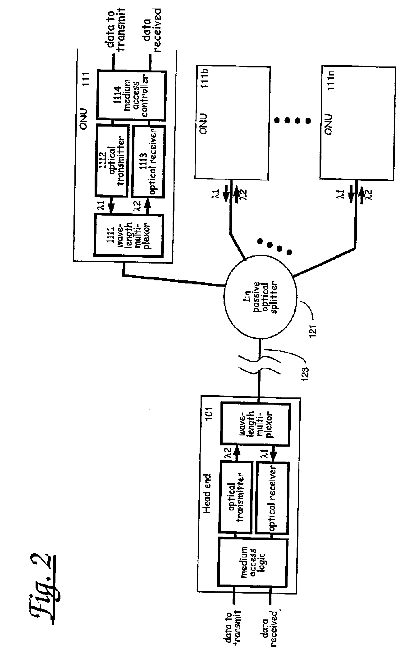
[0052] Fibre based access networks intended for delivery of high bandwidth services to end customers can be based on so-called Passive Optical Networks (PON's). FIG. 1 shows a typical network configuration using a PON. In a PON a headend 101, which is typically located at the network operator's local point of presence or premises 10, is connected to a number of optical network units (ONU's) 111 via a fibre network 12 comprising, for example multiple optical fibre paths 122 linked by a passive optical coupler 121 to provide shared upstream communication and point-to-multipoint downstream communication. The network operator typically provides to the customer a number of services 104, 105, either locally from servers located on the operator's premises, or remotely using data links 107 to other sites. In a ne...


PUM


Abstract

A method and apparatus for filtering data packets in a shared-medium or point-to-multipoint communications network. A filter unit is sent a data packet carrying a filter tag value in a packet addressed to the filter unit. The value is stored in the filter unit and subsequently received packets not addressed to the filter unit itself are forwarded only if they carry the stored filter tag. An embodiment of particular interest applies the method to Ethernet frames over a telecommunications access network (including optical or wireless networks), and uses the VLAN tag field to carry the filter tag information.

Description

[0001] This is the non-provisional filing of Provisional U.S. Application No. 60 / 290,948 filed on May 14, 2001.[0002] The present invention relates to a method and apparatus for filtering streams of data packets in a shared medium or point-to-multipoint communications system and a system incorporating the same.BACKGROUND TO THE INVENTION[0003] There are many known examples of communications network architectures which make use of shared medium communication between a transmitter and multiple receivers. Architectures include for example point-to-multipoint optical networks and wireless networks, in particular for (but not limited to) telecommunications access networks. Whilst these architectures have many problems in common, they are described here in the context of Passive Optical Networks (PON's) in general and Gigabit Ethernet PON's (GEPON's) in particular,[0004] GEPON's have been proposed as a means of cost effectively providing fibre access to homes and businesses. In such a net...

Claims


Application Information

Patent Timeline
IPC IPC(8): H04L12/18H04L29/06
CPCH04L12/1836H04L69/22H04L29/06H04L12/1886H04L9/40
Inventor UNITT, BRIANGRANT, MICHAELPHILLIPS, DAVIDALLEN, MATTHEW JOHN
Owner RPX CLEARINGHOUSE
Learn More