

Method and system for location management and location information providing system
a technology of location management and location information, applied in navigation instruments, wireless commuication services, instruments, etc., can solve the problems of increasing communication traffic volume, cumbersome and expensive to provide such devices, and base stations and switches still have to process large amounts of data
- Summary
- Abstract
- Description
- Claims
- Application Information
AI Technical Summary
Benefits of technology
Problems solved by technology
Method used
Image

Examples
first embodiment
1-1. Configuration of a Communication System of First Embodiment
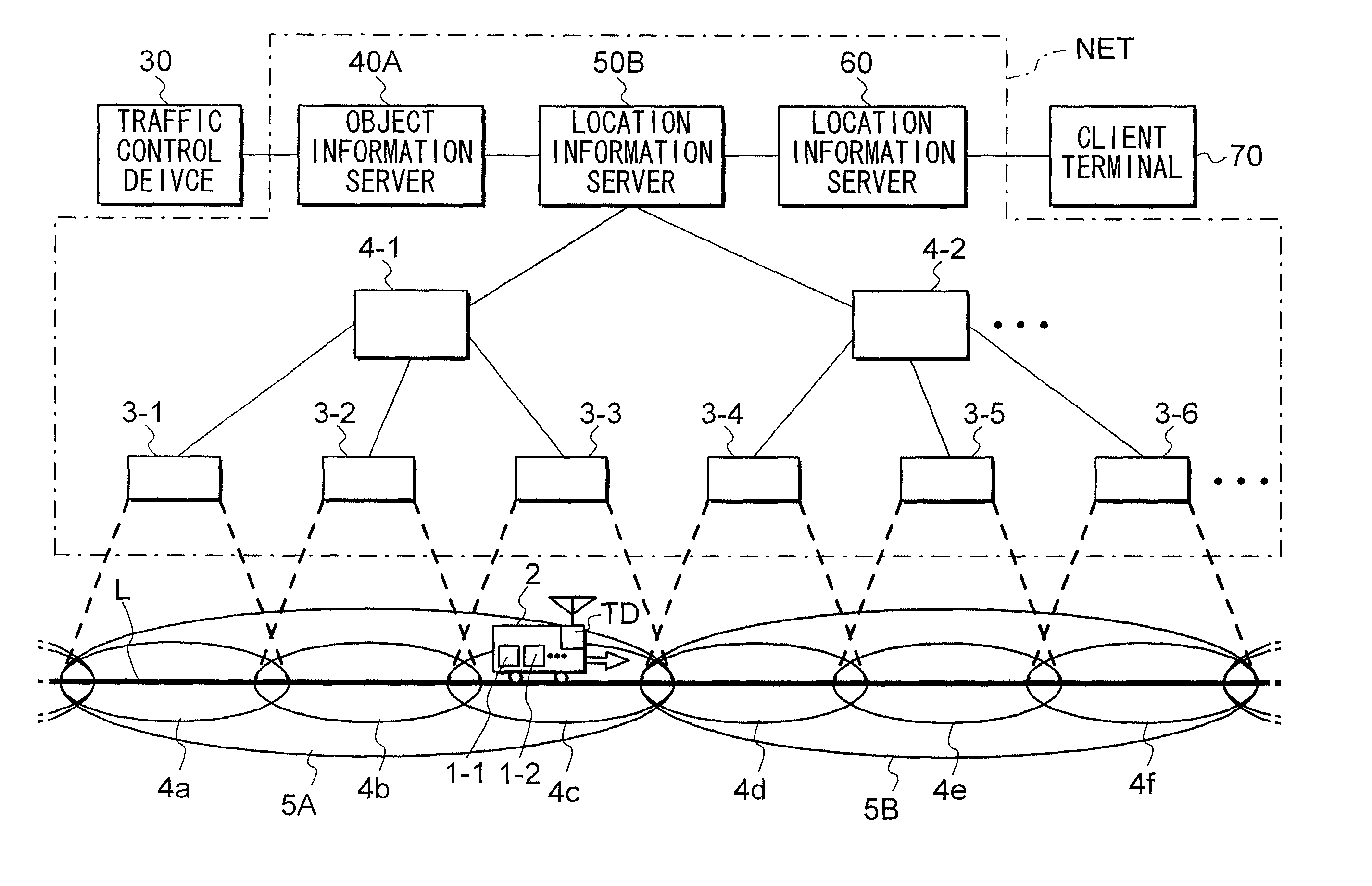
[0058] FIG. 1 illustrates a wireless communication system based on the first embodiment of the invention. As shown in FIG. 1, the system comprises a mobile network NET, a moving object 2, and a traffic control device 30. Object 2 is, for example, a train, a bus, and other means of transportation. It will now be described assuming that Moving object is a train In the figure only a moving object 2 is illustrated but in actuality, many trains 2 exist in the system. Traffic control device 30 manages movements of the trains. Traffic controls device 30 keeps track of each train, specifically, has present location, train schedule, and other information related to the train such as delay. Also, Traffic control device 30 generates movement information INFx, which is the latest information on a movement of an object, to transmit other devices.
[0059] Movement information INFx includes object location information INF1 on a location...
second embodiment
2. SECOND EMBODIMENT
2-1. Configuration of a Communication System
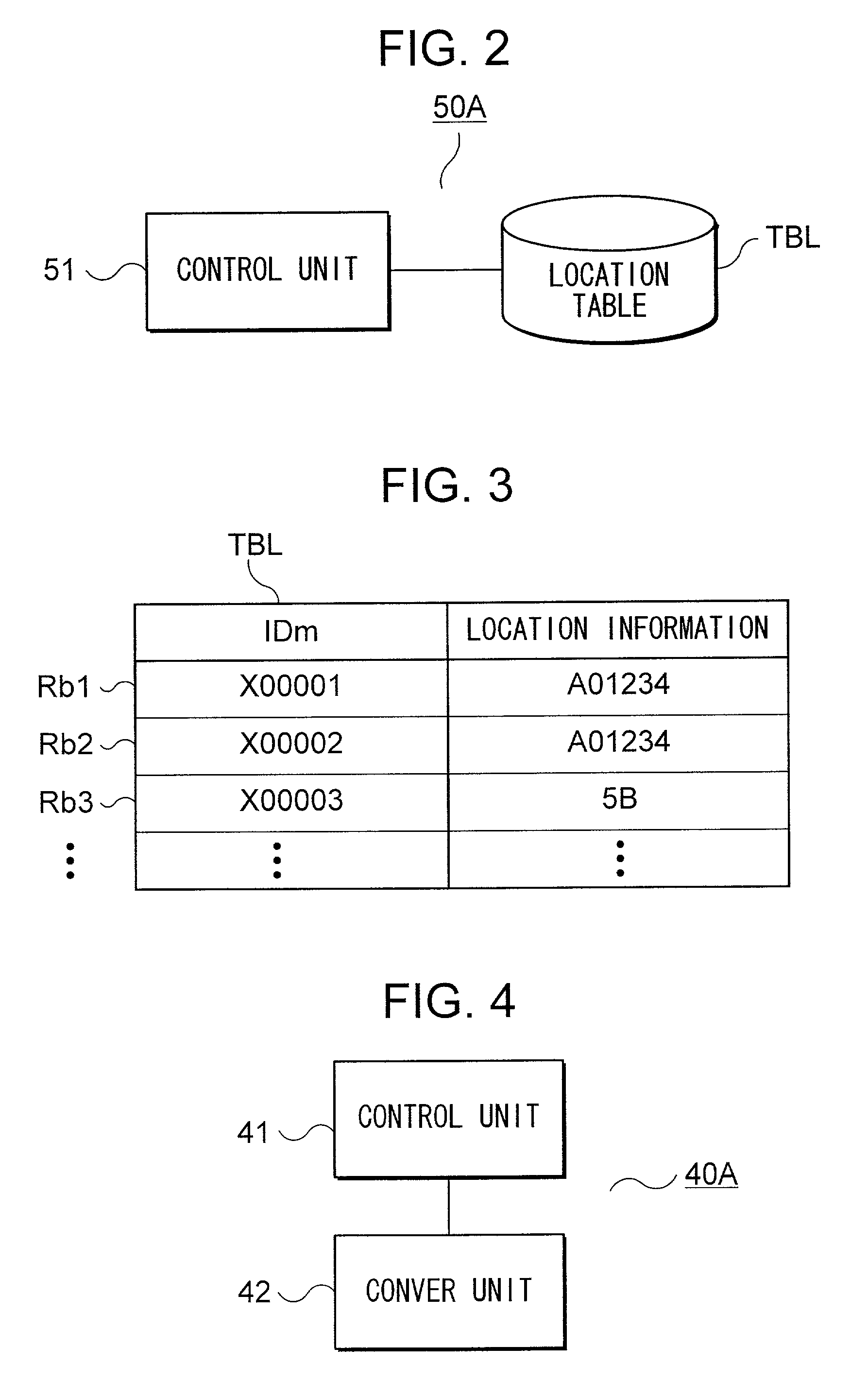
[0079] A wireless communication system based on the second embodiment is similar to that of the first embodiment, except that a location server 50B is introduced instead of Location server 50A.
[0080] FIG. 6 is a schematic block diagram of Location server 50B. As shown, Location server 50B has a control unit 51, first location table TBL1, and second location table TBL2. Second location table TBL2 is the same as Location table of the first embodiment. FIG. 7 shows details of the First location table and Second location table. First location table TBL1 has a plurality of records Ra1, Ra2, . . . , each storing Object ID number IDt and location area information INF correspondingly. It is noted that the records and Objects 2 are same in number. For example, if Object 2 is located within a location area 5A and Object ID number IDt is "A01234", "A01234" and "5A" are stored in a record Ra1 of First location table TBL1 as shown i...
third embodiment
3. THIRD EMBODIMENT
[0087] An information providing system based on the third embodiment is an application of the system based on the second embodiment.
3-1. Configuration of the System
[0088] FIG. 9 is a schematic diagram of the system of this embodiment. This system differs from that of the second embodiment only in having a Location information server 60, Client terminal 70, and Mobile station 1A instead of Mobile station 1. Client terminal 70 is, for example, a Personal Computer (PC), Personal Digital Assistants (PDA), mobile phone, and other communication devices, which carry out communication with Location information server 60.
[0089] FIG. 10 is a schematic block diagram of Location information server 60. As shown, Location server has a Central Processing Unit (CPU) 61, Read Only Memory (ROM) 62, Random Access Memory (ROM) 63, Interface 64, and Hard disk 65. Location information server 60 provides location information of Mobile station 1A responsive to a request from Client termi...
PUM
 Abstract
Description
Claims
Application Information