Lithographic apparatus, device manufacturing method, and device manufacturing thereby

a technology of lithographic apparatus and manufacturing method, applied in the direction of printers, machine supports, domestic objects, etc., can solve the problems of affecting the accuracy of lithographic projection, and the difficulty of achieving the desired degree of stability

Inactive Publication Date: 2002-10-17
ASML NETHERLANDS BV
View PDF4 Cites 70 Cited by
  • Summary
  • Abstract
  • Description
  • Claims
  • Application Information

AI Technical Summary

Problems solved by technology

Transient inaccuracies in this relative position, which may be caused by vibrations, may be detrimental to this accuracy.
The desired degree of stability can therefore be very difficult to achieve.

Method used


Image

  • Lithographic apparatus, device manufacturing method, and device manufacturing thereby
  • Lithographic apparatus, device manufacturing method, and device manufacturing thereby
  • Lithographic apparatus, device manufacturing method, and device manufacturing thereby

Examples


embodiment 1

[0048] Embodiment 1

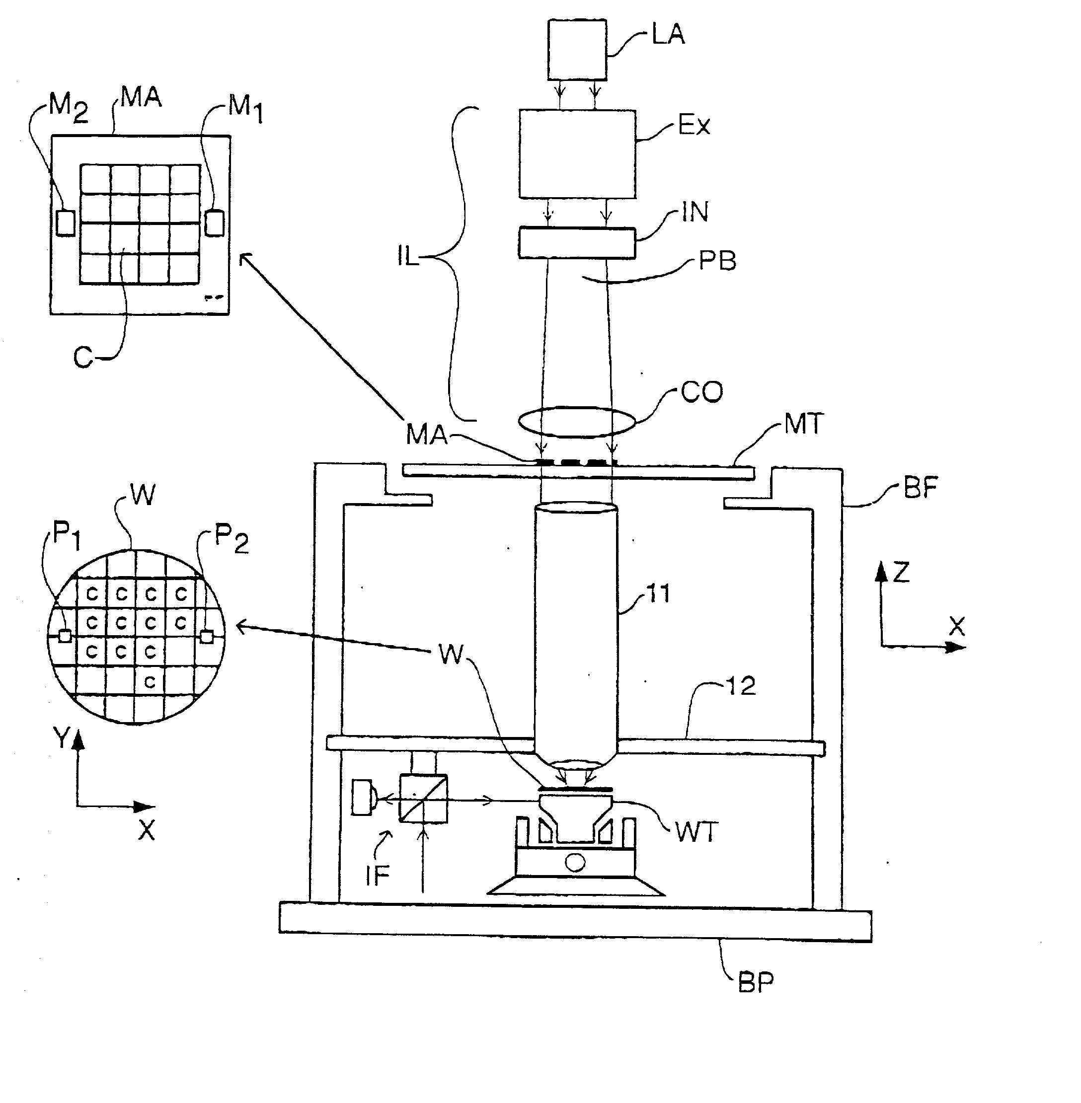
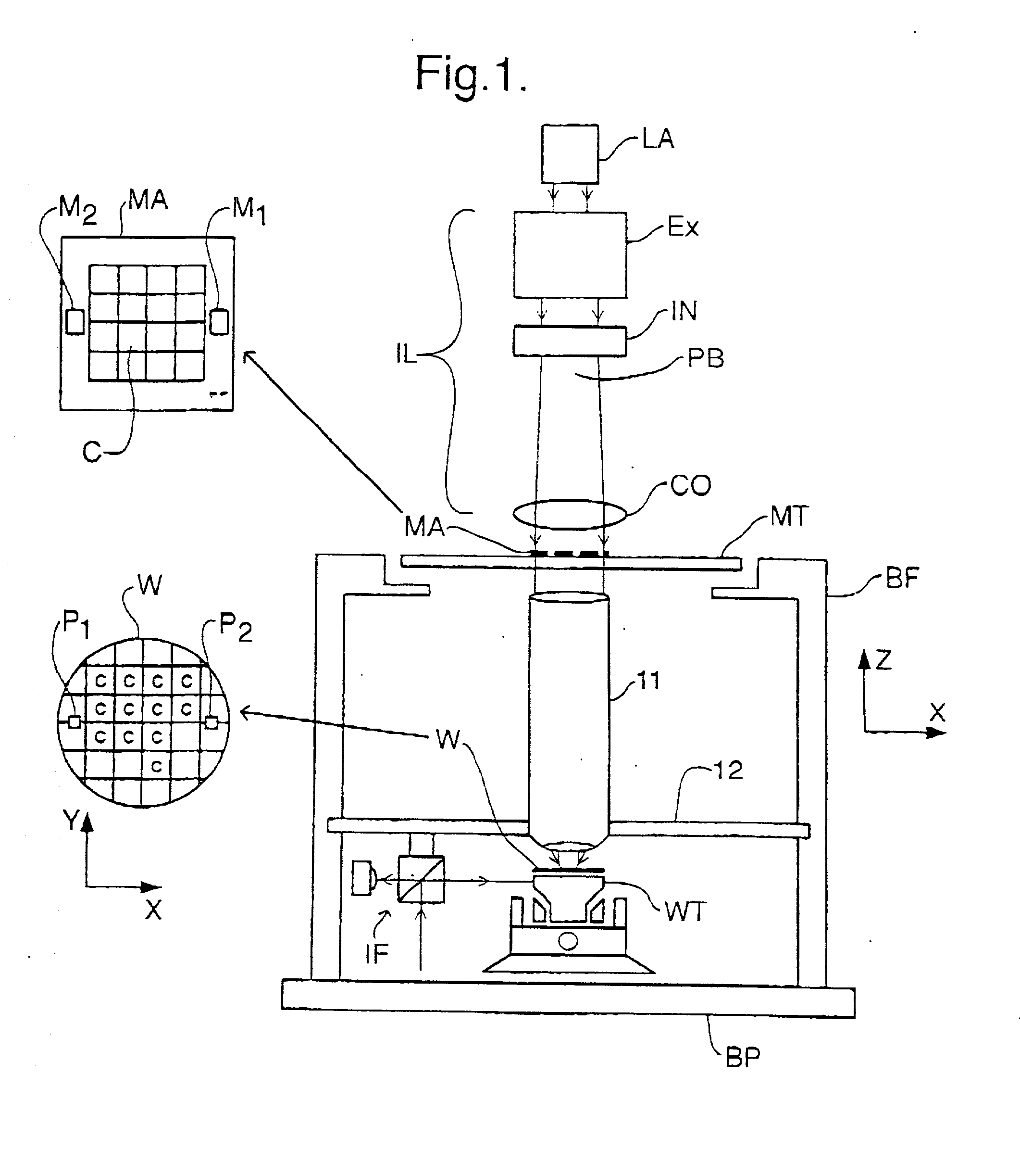
[0049] FIG. 1 schematically depicts a lithographic projection apparatus according to a particular embodiment of the invention. The apparatus comprises:

[0050] a radiation system LA, Ex, IL for supplying a projection beam PB of radiation (e.g. UV or EUV radiation, electrons or ions);

[0051] a first object table (mask table) MT provided with a mask holder for holding a mask MA (e.g. a reticle);

[0052] a second object table (substrate table) WT provided with a substrate holder for holding a substrate W (e.g. a resist-coated silicon wafer), and connected to positioning means for accurately positioning the substrate with respect to item 11;

[0053] a projection system ("lens") 11 (e.g. a refractive or catadioptric, a mirror group or a set of field deflectors) for imaging an irradiated portion of the mask MA onto a target portion C (comprising one or more dies) of the substrate W.

[0054] As here depicted, the apparatus is of a transmissive type (i.e. has a transmissive mask)....

embodiment 2

[0080] Embodiment 2

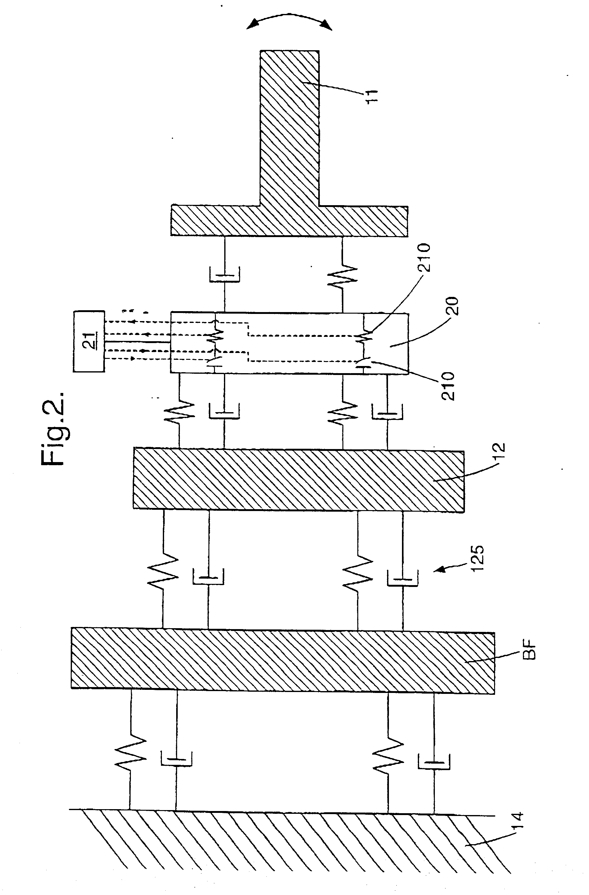
[0081] FIGS. 6 and 7 describe further embodiments of the invention. The silent world 13 comprising the projection system 11 and the main plate 12 is suspended from the rest of the lithographic apparatus by airmounts 125. The silent world 13 is also provided with the optical measurement system OM that is used in a twin stage lithographic projection apparatus to perform measurement of the substrate topology using alignment sensors and leveling sensors at the measurement position. Twin stage lithographic apparatus are described, for example, in U.S. Pat. No. 5,969,441 and U.S. Ser. No. 09 / 180,011, filed Feb. 27, 1998 (WO 98 / 40791), incorporated herein by reference. The silent world may also be provided with an interferometry system for determining the position of the substrate table WT in a lithographic projection apparatus. That the projection system 11 and the optical measurement system OM are both in the same silent world 13 and that there is a very rigid connecti...


PUM

PropertyMeasurementUnit
frequencyaaaaaaaaaa
frequenciesaaaaaaaaaa
massaaaaaaaaaa

Abstract

Vibrational movement between the top of a lens and a main plate on which the lens is mounted is reduced by attaching between the lens and the main plate a lens support which detects relative movement between the lens and the main plates using piezoelectric sensors and compensates for that movement to reduce vibration using piezoelectric actuators which are in series with the piezoelectric sensors. The control signal which is generated to actuate the actuated piezoelectrics is generated by a controller.

Description

[0001] The present invention claims priority from European Patent application No. 01300479.1 filed Jan. 19, 2001 and herein incorporated by reference.[0002] 1. Field of the Invention[0003] The present invention relates to lithographic projection apparatus and more particularly to lithographic projection apparatus including a vibration isolation system.[0004] 2. Description of the Related Art[0005] Lithographic projection apparatus in accordance with the present invention generally include a radiation system for supplying a projection beam of radiation, a support structure for supporting patterning structure, the patterning structure serving to pattern the projection beam according to a desired pattern, a substrate table for holding a substrate, and a projection system for projecting the patterned beam onto a target portion of the substrate.[0006] The term "patterning structure" should be broadly interpreted as referring to means that can be used to endow an incoming radiation beam w...

Claims


Application Information

Patent Timeline
Patent Type & Authority Applications(United States)
IPC IPC(8): G03F7/20H01L21/027
CPCG03F7/709G03F7/70833H01L21/027
Inventor AUER, FRANKSPANJERS, FRANCISCUS ANDREAS CORNELIS JOHANNES
Owner ASML NETHERLANDS BV
Why Eureka
Try Eureka