Optical switch

Inactive Publication Date: 2002-10-17
MINOLTA CO LTD
View PDF2 Cites 122 Cited by
  • Summary
  • Abstract
  • Description
  • Claims
  • Application Information

AI Technical Summary

Benefits of technology

[0011] According to this configuration, by moving the switching member, the switching positions disposed on the optical path can be changed over, and lights of at least two different wavelengths can be guided selectively into the first direction or second direction. Further, by properly setting the position of the switching member, both switching positions can be kept away from the optical path. Therefore, for example, when the switching member is moved away from the optical path of the optical waveguide, the wavelength multiplexed incident light runs forward straightly, and when the switching member is disposed on the optical path of the optical waveguide, light of one wavelength passes and light of other wavelength is reflected.

Problems solved by technology

According to such conventional optical switch, however, the lights multiplexed in wavelength are uniformly reflected or transmitted, and pieces of information put on different carriers cannot be issued separately.
Accordingly, information is taken out by filtering by a branching filter, and the optical communication system having the optical switch is complicated in configuration.
As a result, the optical switch is complicated in either case.

Method used


Image

  • Optical switch
  • Optical switch
  • Optical switch

Examples


examples of experiment

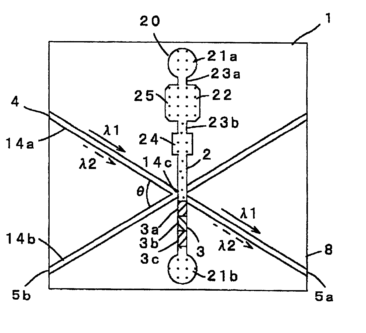
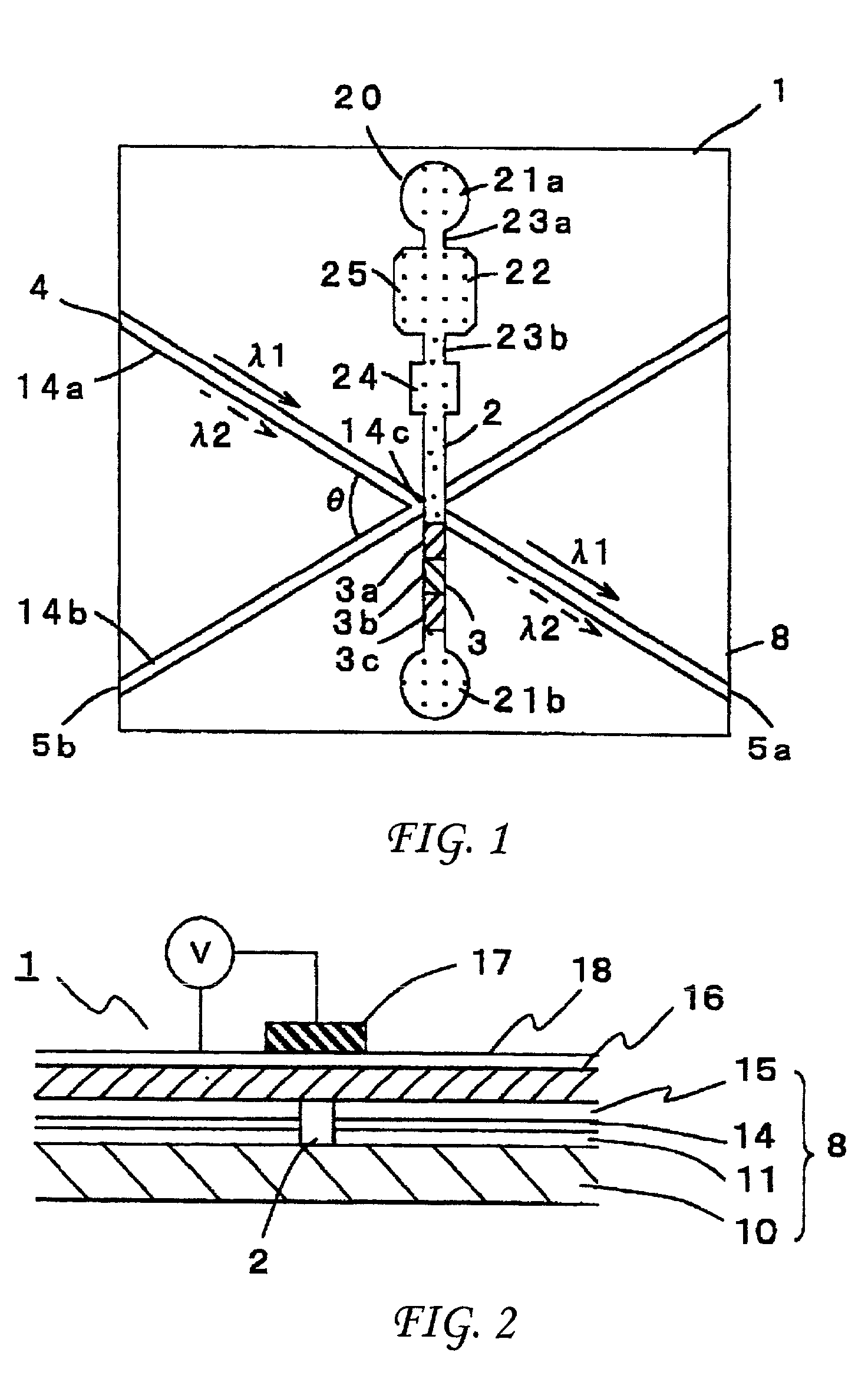
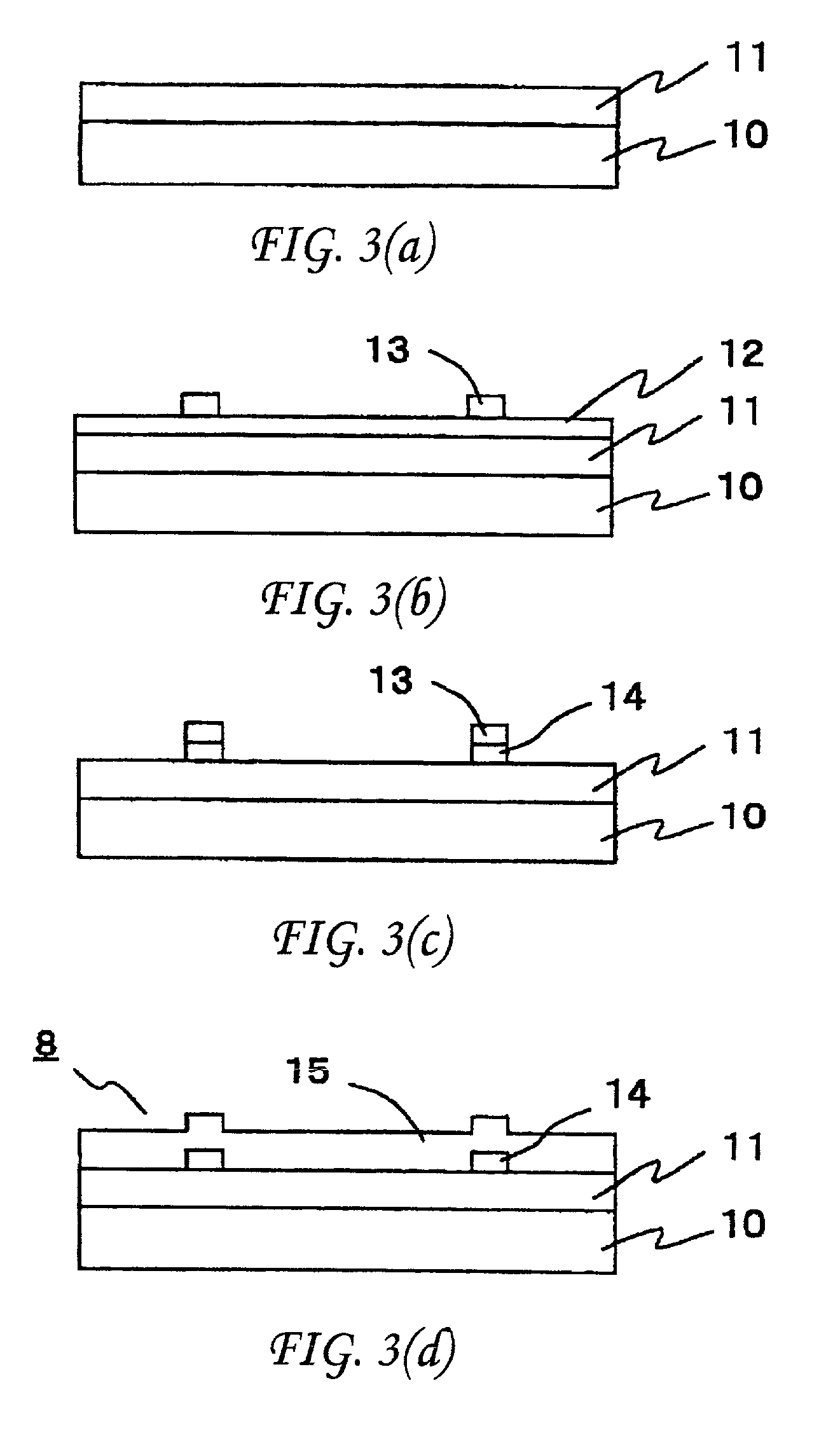
[0061] The optical switch 1 of embodiment 1 was manufactured in the following specification, and the operation of the optical switch 1 was evaluated. The interference filters 3a to 3c were manufactured according to the optical characteristics shown in FIG. 8 to FIG. 10.

1TABLE Specification of Optical Switch 1 Main Substrate Material Silicon body Lower clad layer Material Quartz Thickness 20 .mu.m Refractive index 1.4626 Waveguide Material Quartz Thickness 7 .mu.m Refractive index 1.4670 Crossing angle .theta. 10.degree. Upper clad layer Material Quartz Thickness 20 .mu.m Refractive index 1.4626 Groove Depth 100 .mu.m Diffuser Depth d .times. width w 25 .mu.m .times. 20 .mu.m Diaphragm Material Borosilicate glass Thickness 70 .mu.m Piezoelectric element Material PZT Max. voltage 60 V Frequency 11 kHz Matching oil Refractive index 1.4626 Filter Substrate Material Fluorinated polyimide Thickness 5 .mu.m Refractive index 1.52 Interference filter Material Lamination of SiO.sub.2 and TiO....


PUM


Abstract

Disclosed herein is an optical switch for changing over a running direction of a light passing through an optical waveguide between a first direction and a second direction by moving a switching member disposed on an optical path of an optical waveguide. The switching member has a plurality of switching positions for selectively guiding each of lights of at least two different wavelengths into the first direction or second direction.

Description

[0001] This application is based on Japanese Patent Application No. 2001-001724 filed in Japan on Jan. 9, 2001, the entire content of which is hereby incorporated by reference.[0002] 1. FIELD OF THE INVENTION[0003] The present invention relates to an optical switch for reflecting or transmitting light by a switching member disposed on an optical path of an optical waveguide, and changing the running direction of light by the moving of the switching member.[0004] 2. DESCRIPTION OF THE RELATED ART[0005] A conventional optical switch is disclosed, for example, in Japanese Unexamined Patent Publication No. 2000-121967A. In this optical switch, a micro mirror disposed on an optical path of luminous flux emitted from an optical fiber is supported by a movable plate, and the movable plate is moved by applying a voltage to move the micro mirror away from the optical path, so that forwarding and reflecting of light are changed over.[0006] On the other hand, U.S. Pat. No. 5,699,462 discloses ...

Claims


Application Information

Patent Timeline
IPC IPC(8): G02B6/12G02B26/08G02B6/34G02B6/35
CPCG02B6/12007G02B6/125G02B6/3578G02B6/3538G02B6/355G02B6/29368
Inventor NISHIDA, NAOKIHATANO, TAKUJITAKAHARA, KOJIMARUYAMA, SHINJITERAMOTO, MIYUKISEKINE, KOUJIROU
Owner MINOLTA CO LTD
Why Eureka
Try Eureka