
Hair removing device with a lotion applicator

Inactive Publication Date: 2002-10-31
MATSUSHITA ELECTRIC WORKS LTD
View PDF6 Cites 13 Cited by
  • Summary
  • Abstract
  • Description
  • Claims
  • Application Information

AI Technical Summary

Benefits of technology

[0006] Thus, the applicator is enabled to dispense the lotion over the skin where the hair removing is made or being made without requiring an extra and cumbersome switching work to the user. That is, the user can enjoy the hair removing supplemented with the lotion, yet without being bothered to manipulate a particular switch or handle.
[0007] Preferably, the actuator is included in the applicator in a skin-contact relation with the skin and is movable relative to the housing so as to actuate the lotion supply mechanism when it is depressed as a result of the applicator being pressed against the user's skin. With this arrangement, the user is only required to bring the applicator in contact with the skin for feeding the lotion, making it possible to feed the lotion properly while making the hair removing, yet without being conscious of the actuator.
[0008] The applicator may be configured to include a header having a chamber for temporarily storing the lotion supplied from the tank. The header has at least one aperture which communicates with the chamber and is fifed with a rotating element such as a ball and a roller that defines the actuator. The rotating element is held rotatable in the aperture so as to come into rolling contact with the user's skin for applying the lotion over the skin. Thus, it is easy to feed the lotion smoothly over the skin with the aid of the rotating element.

Problems solved by technology

Thus, the user has to repeat turning on and ff the pump until finishing the shaving, otherwise the pump would be activated continuously to dispense the liquid wastefully.

Method used


Image

  • Hair removing device with a lotion applicator
  • Hair removing device with a lotion applicator
  • Hair removing device with a lotion applicator

Examples


first embodiment

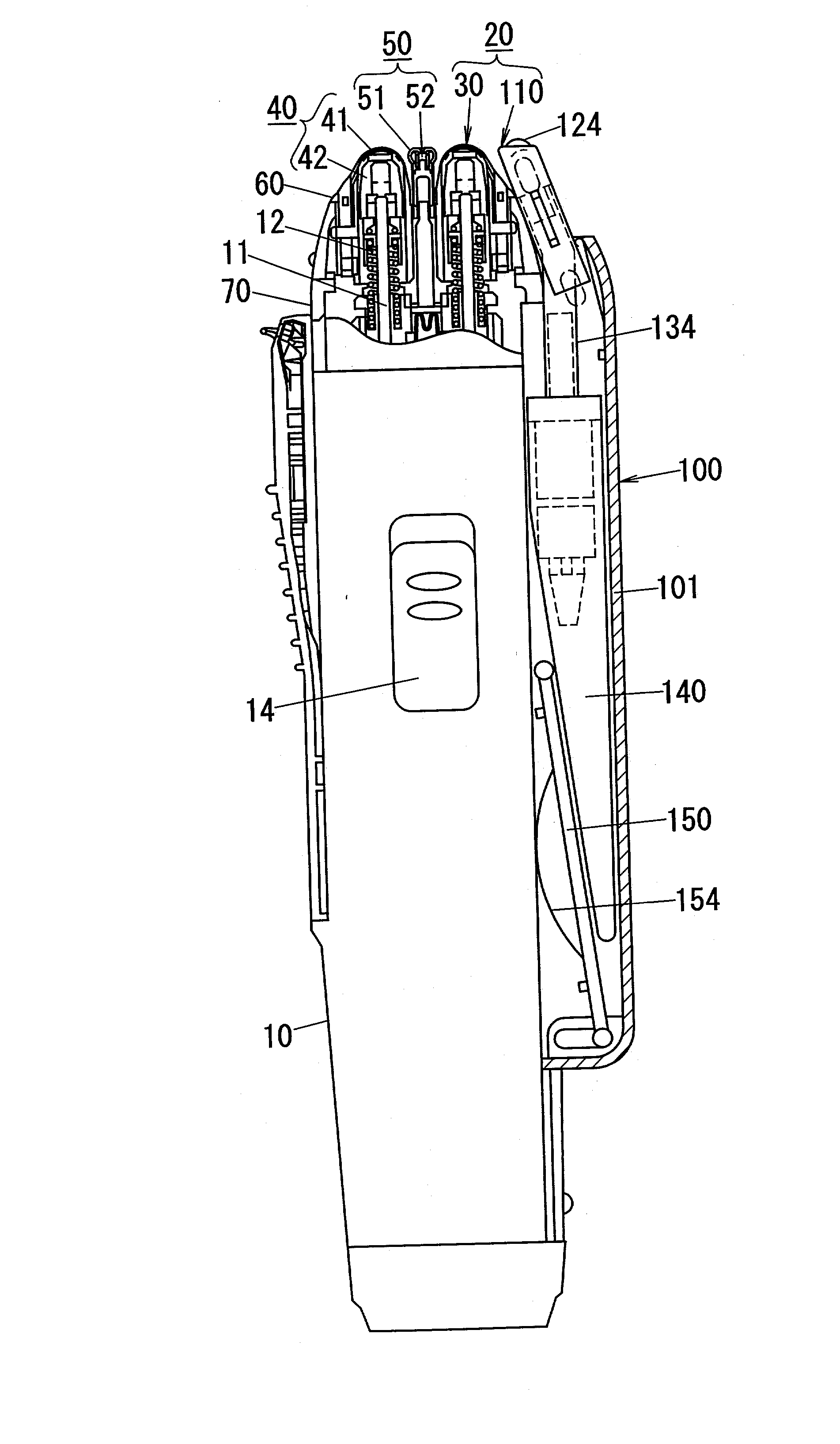
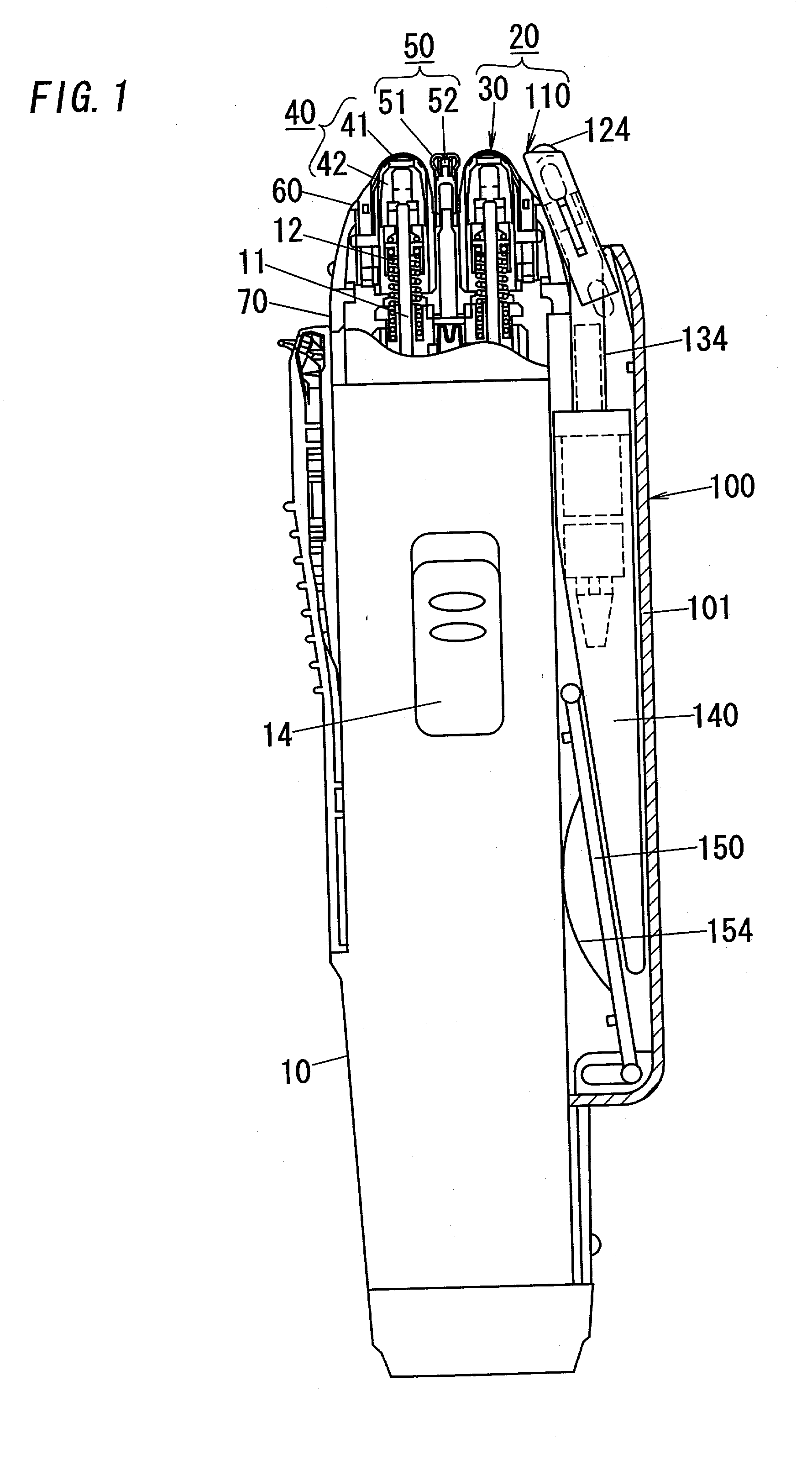
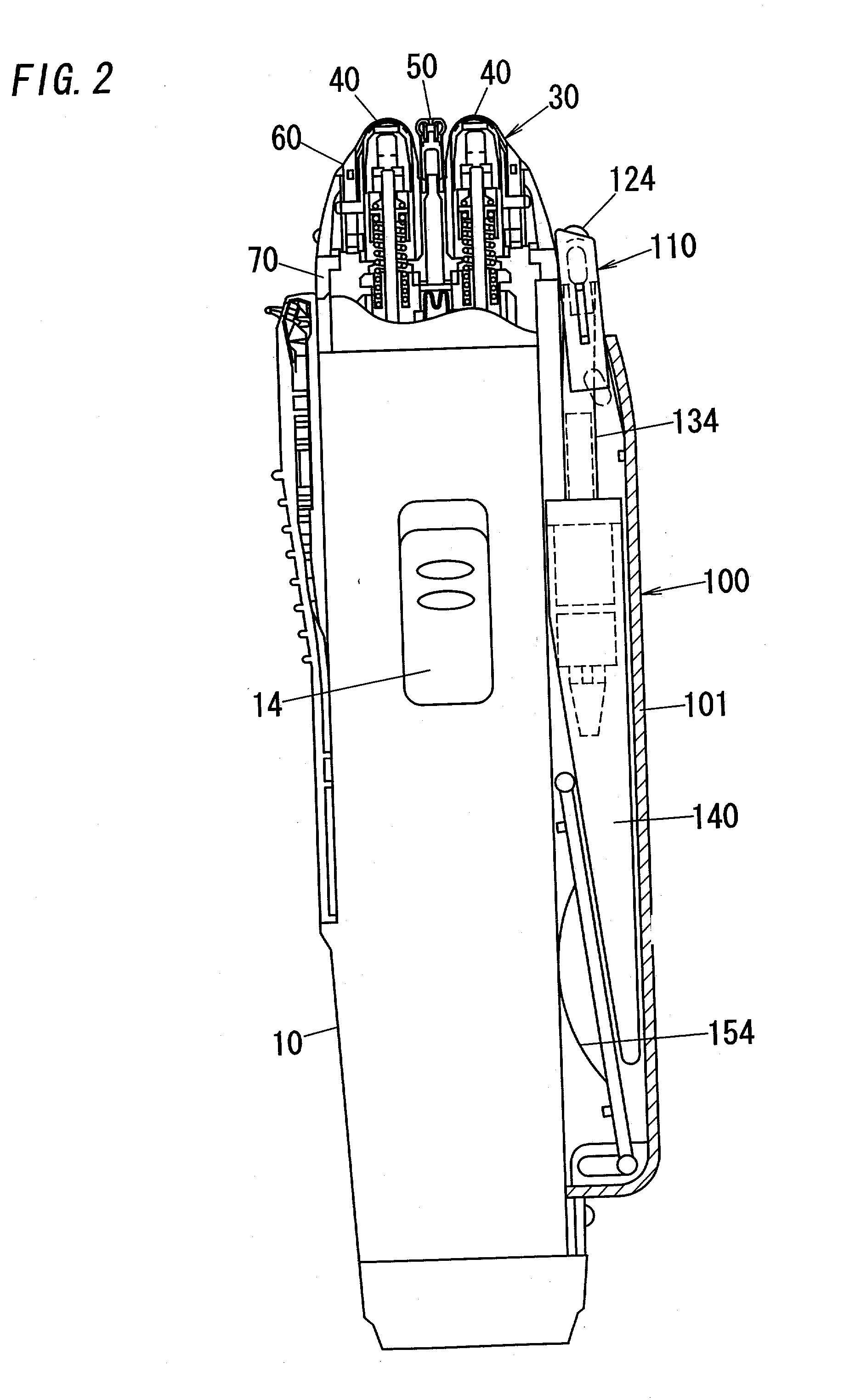
[0062] Referring now to FIG. 1, there is shown a dry shaver as one typical version of the personal hair removing device in accordance with the present invention. The shaver includes a housing 10 to be grasped by a hand of a user, and a treatment head 20 which projects on top of the housing 10 and includes a shaving unit, i.e., or hair removing unit 30 as well as an applicator 110 for feeding a lotion on a user's skin. The hair removing unit 30 is composed of three hair cutting sections, namely, a pair of short-hair cutters 40 and a long-hair cutter 50 interposed between the short-hair cutters 40. The short-hair cutter 40 has a U-shaped outer shearing foil 41 and an inner cutter 42 which is driven to oscillate in shearing engagement with the foil, while the long-hair cutter 50 is composed of a slender outer cutter 51 and an inner cutter 52 driven to oscillate in shearing engagement with the outer cutter. The outer shearing foil 41 and the long hair cutter 50 are floatingly supported ...

second embodiment

FIGS. 21A and 21B

[0074] Referring to FIGS. 21A and 21B, there is shown an applicator of another type which can be utilized in the device. The applicator 110F of the present embodiment is provided with a pump 160 for drawing the lotion from the tank and delivering it to a chamber 113F in the applicator for dispensing the lotion therefrom over the user's skin. For this purpose, the applicator 110F has the header 111F so configured that a floating bed 120F is cooperative with a bottom wall 114F to define the pump 160 having a pump chamber 161 which communicates with the tank through an inlet flap valve 162 and communicates with the chamber 113F through an outlet flap valve 164. In this sense, the pump 160 is defined as one element for constituting the lotion supply mechanism for supplying the lotion from the tank to the applicator. The floating bed 120F is floatingly supported to the bottom wall 114F by means of coil springs 121 F to be movable relative to the bottom wall while changin...

third embodiment

FIGS. 23 to 25

[0077] Referring to FIGS. 23 to 25, there is shown a hair removing device in accordance with a third embodiment of the present invention which is identical in structure to the first embodiment except that an applicator 110H is incorporated into a shaving unit 30H and that a diaphragm pump 160H is disposed just below the shaving unit. Thus, the shaving unit 30H assumes an appearance of a treatment head 20H. The structures and operation of the shaving unit 30H are identical to those in the first embodiment. Therefore, no duplicate explanation is made herein. Like parts are designated by like reference numerals with a suffix letter of "H". The pump 160H is mounted on top of the housing 10H with its inlet connected to a tank 140H by means of the flexible tube 134H and with its outlet connected to an upright extending duct 166. The pump 160H has a diaphragm 170 with a lever 172 which is held in an abuttable relation with a cassette 44 carrying the shearing foils of the shor...


PUM


Abstract

A hair removing device capable of feeding a lotion in association with a hair removing operation. The device has a treatment head that is mounted on a housing and includes a hair removing unit for hair depilation or hair epilation and an applicator for supplying a lotion on a user's skin. Also included in the device is a tank holding the lotion and a lotion supply mechanism for supplying the lotion from the tank to the applicator. The treatment head is formed with an actuator which acknowledges an even of the treatment head coming into an operative condition with the skin and activates a lotion supply mechanism to supply the lotion from the tank to the applicator when such event is acknowledged.

Description

[0001] 1. Field of the Invention[0002] The present invention is directed to a hair removing device with a lotion applicator, and more particularly to the personal hair removing device capable of feeding a lotion for facilitating the hair treatment as well as for making a skin care.[0003] 2. Description of the Prior Art[0004] WO98 / 08661 and Japanese Utility Model Publication No. 59-108574 disclose a portable shaver capable of feeding a lotion for facilitating the shaving. The shaver incorporates a pump which is activated by a button or switch to feed the lotion over a user's skin where the shaving is intended. The button or switch is mounted on a shaver housing to be accessibly by a finger of the user grasping the housing, so that the user is required to manipulate the button or the switch each time the lotion feeding is desired. However, it is a normal shaving practice to move the shaver intermittently across the skin, i.e., moving from one portion to another portion of the skin thr...

Claims


Application Information

Patent Timeline
IPC IPC(8): B26B19/44A45D26/00A45D34/04B26B19/40
CPCA45D26/0023A45D34/04B26B19/40A45D2026/0095A45D2026/009B26B19/44
Inventor SAITOU, ATSUHIROIWASAKI, JYUZAEMONARAKI, MASAKATSUTANAKA, HIDEKIYAMASAKI, MASANOBUKATOU, HIROKAZU
Owner MATSUSHITA ELECTRIC WORKS LTD
Learn More