Storage array employing scrubbing operations at the disk-controller level

a technology of disk controller and storage array, applied in the direction of digital signal error detection/correction, coding, instruments, etc., can solve the problems of multiple disk arrays, increased failure rates, and inability to provide data redundancy

Inactive Publication Date: 2002-10-31
ORACLE INT CORP
View PDF9 Cites 179 Cited by
  • Summary
  • Abstract
  • Description
  • Claims
  • Application Information

AI Technical Summary

Problems solved by technology

Unfortunately, one disadvantage of using arrays of multiple disks is increased failure rates.
However, a disadvantage of RAID 0 systems is that they do not provide for any data redundancy and thus are not fault tolerant.
Because all parity information is stored on a single disk, however, the parity disk must be accessed every time data is sent to the array, and this may create a performance bottleneck.
One drawback of RAID levels 3, 4, and 5 is that write performance may suffer due to the overhead required to calculate parity information.
When storage arrays provide redundant data, their ability to reconstruct lost data may depend on how many failures occurred.
For example, some RAID systems may only be able to tolerate a single disk failure.
Once a single disk fails, such systems are said to be operating in a degraded mode because if additional disks fail before the lost data on the failed disk has been reconstructed, it may no longer be possible to reconstruct any lost data.
The longer a storage array operates in a degraded mode, the more likely it is that an additional failure will occur.
An additional potential problem in any storage array is that errors other than total disk failures may occur, and like disk failures, these errors may cause data vulnerability or data loss.
For example, disk drives may occasionally corrupt data.
For example, bugs in a disk drive controller's firmware may cause bits in a sector to be modified or may cause blocks to be written to the wrong address.
Such bugs may cause storage drives to write the wrong data, to write the correct data to the wrong place, or to not write any data at all.
Another source of errors may be a drive's write cache.
However, write cache errors may cause some acknowledged writes to never reach the disk media.
The end result of such bugs or errors is that the data at a given block may be corrupted or stale.
These types of errors may be "silent" because the drive may not realize that it has erred.
If left undetected, such errors may have detrimental consequences, such as undetected long-term data corruption.
In storage arrays with no redundancy and no backup system in place, these errors may lead directly to data loss.
Furthermore, such data loss may not even be fixable via backup.
For example, if the data was corrupted when it was written to the storage array, the backups themselves may only contain copies of the corrupted data.
Also, if the backups are only maintained for a relatively short duration, a valid copy of the data may no longer exist.
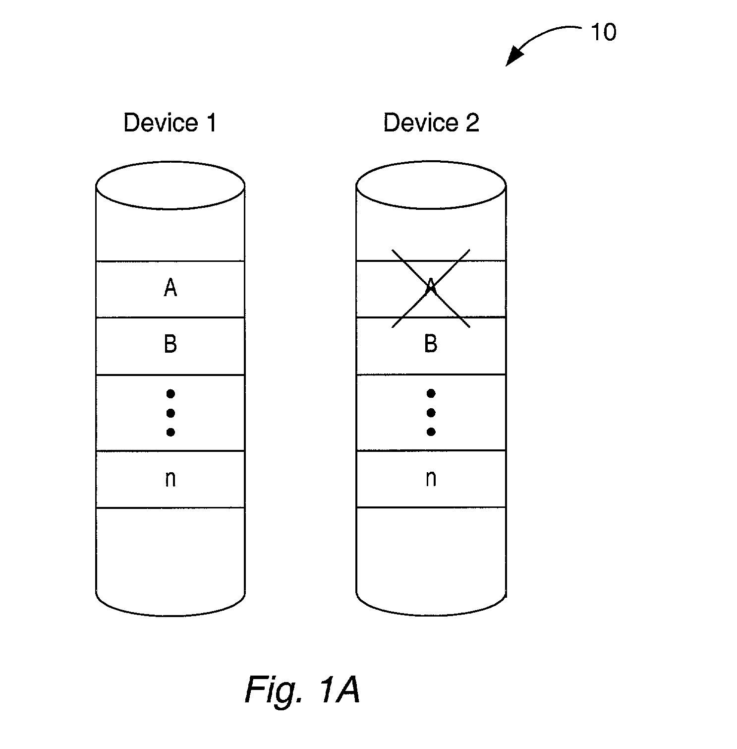
Silent errors pose an additional hazard in arrays that provide redundancy. FIG. 1A shows a storage array 10 that provides redundancy through mirroring.
Subsequently, device 1 may fail.
Some time later, device 2 may experience a failure.
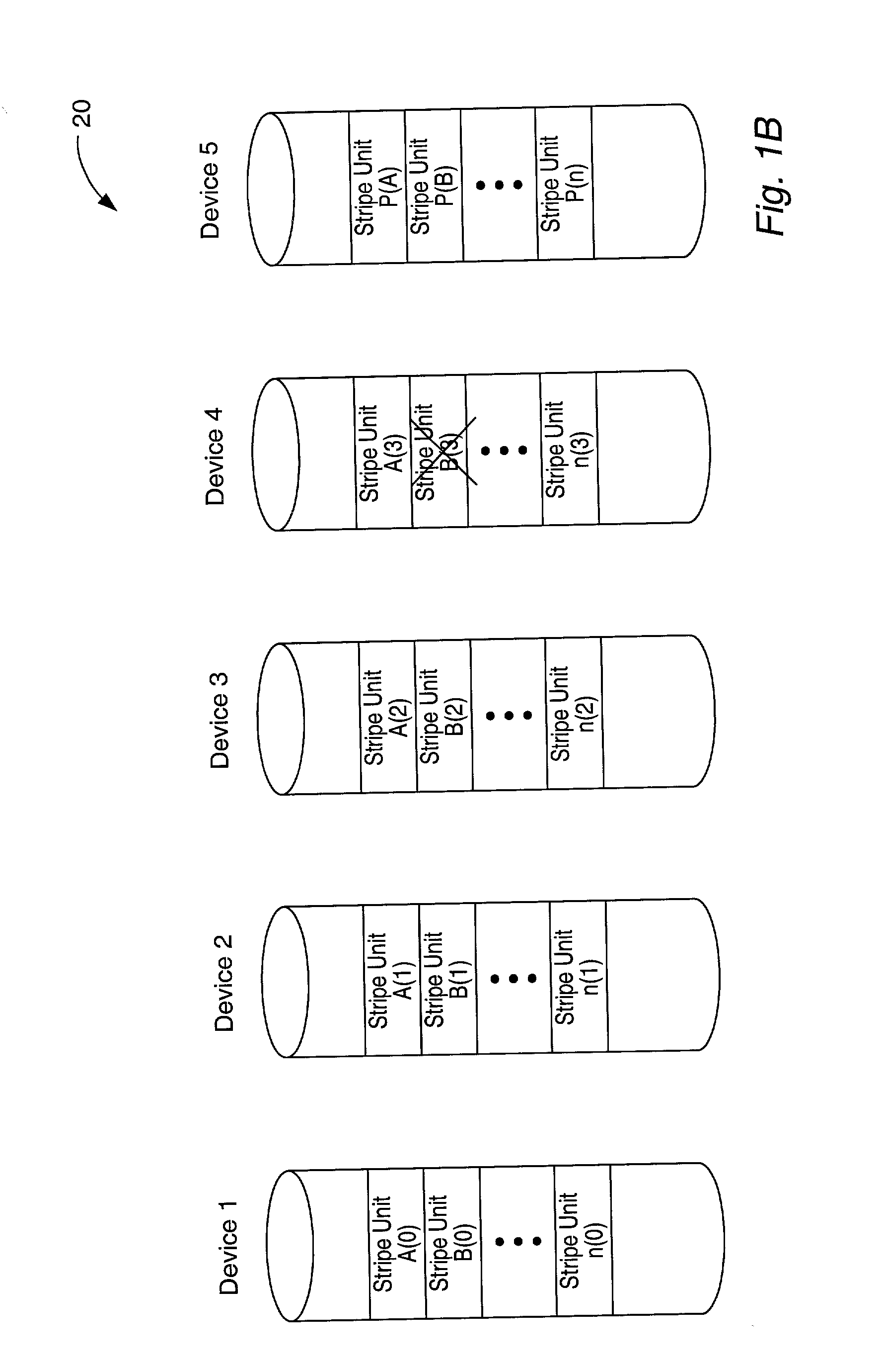
1A and 1B, it may be impossible to restore the corrupted data after a subsequent disk failure unless a valid backup is available.
If the data within the multi-unit data range is erroneous, some embodiments may further pinpoint the location of the error.

Method used


Image

  • Storage array employing scrubbing operations at the disk-controller level
  • Storage array employing scrubbing operations at the disk-controller level
  • Storage array employing scrubbing operations at the disk-controller level

Examples


Embodiment Construction

[0037] FIG. 2A shows an example of a computer system 100 in which embodiments of the invention may be employed. A storage system 150 may be coupled to a computer system 100 by an I / O bus 110. The computer system 100 may include one or more processors 101 and various I / O devices such as a monitor, keyboard, mouse, etc. (not shown). The illustrated computer system includes a processor 101 coupled to a bus bridge unit 105. The bus bridge unit 105 is coupled to a system memory 110 and to a storage system 150. The processor 100 may use the system memory 110 to temporarily store data and software instructions that are accessed rapidly during system operation. The bus bridge 105 may contain hardware to control the system memory 110 and / or the data storage subsystem 150. The I / O bus 110 may connect the bus bridge 105 to the storage system 150 and may be a bus such as the peripheral component interconnect (PCI) bus in some embodiments. In other embodiments, the I / O bus 110 may be implemented...


PUM

PropertyMeasurementUnit
interfaceaaaaaaaaaa
mean time between failureaaaaaaaaaa
timeaaaaaaaaaa

Abstract

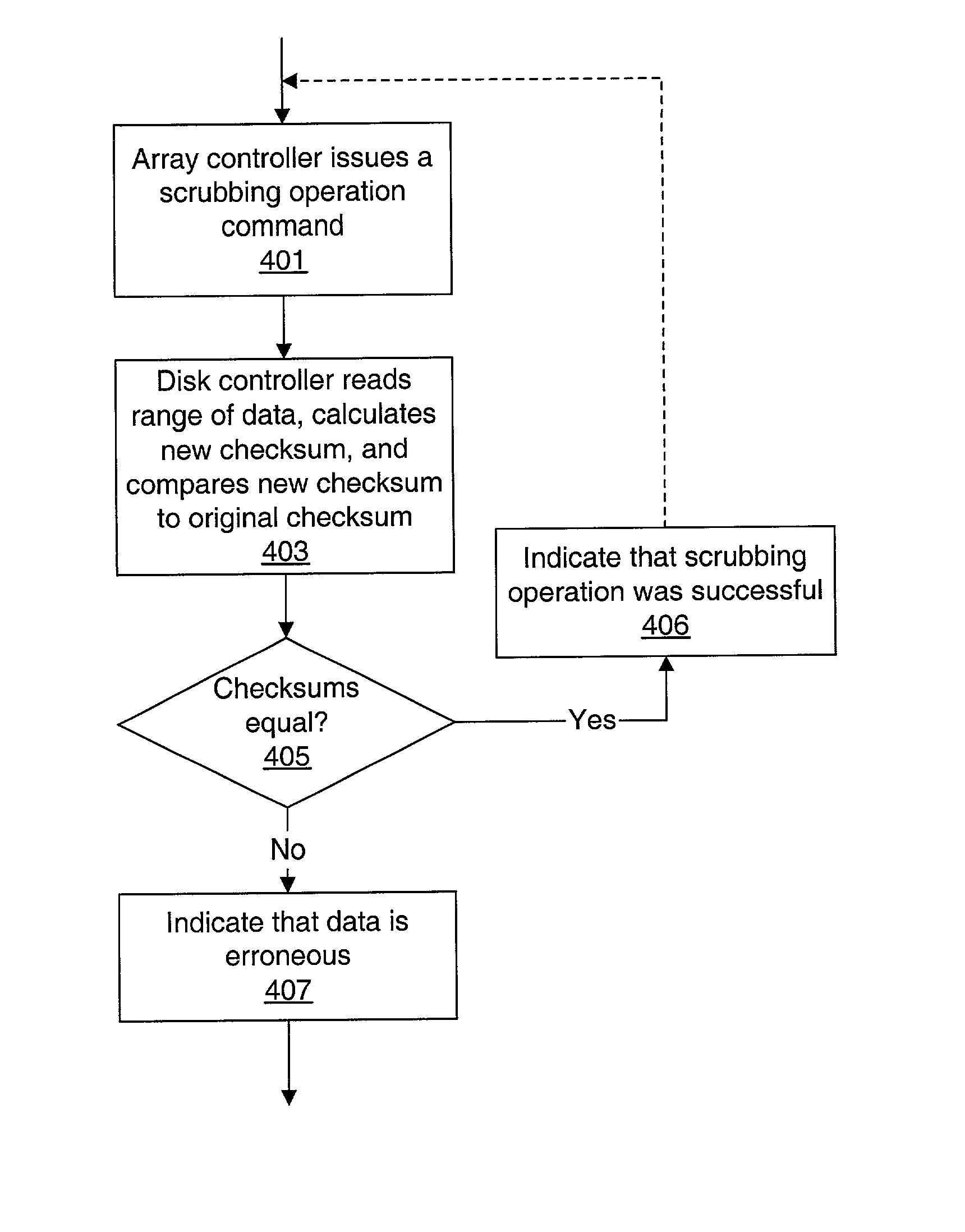
A storage system comprises a storage array controller and a storage array, which includes multiple disk drives and disk drive controllers. The storage array controller issues scrubbing operation commands to one or more of the disk drive controllers. In response, each disk drive controller that receives a scrubbing operation command reads data from within a data range from at least one of the disk drives, calculates a new checksum for the data, and compares the new checksum to a preexisting checksum for the data. If the new checksum doesn't equal the preexisting checksum, the data within the data range is determined to be erroneous.

Description

[0001] This application claims benefit of priority to U.S. Provisional Application Serial No. 60 / 287,937, filed Apr. 30, 2001.[0002] 1. Field of the Invention[0003] This invention relates to error detection in storage systems.[0004] 2. Description of the Related Art[0005] By replacing individual storage devices with arrays of storage devices, the capacity and performance of disk storage systems has been improved. Arrays of storage devices have increased the capacity of disk storage systems by providing more storage capacity than is available using individual disks. Also, because several smaller, less expensive disks can provide the same storage capacity as a single larger, more expensive disk, this increased capacity can often be provided in a relatively cost effective manner. Additionally, some arrays of storage devices are also able to provide increased reliability and / or performance over non-arrayed storage devices.[0006] One example of an array of storage devices is a Redundant ...

Claims


Application Information

Patent Timeline
Patent Type & Authority Applications(United States)
IPC IPC(8): G11B20/18
CPCG06F11/1076G11B20/18G06F2211/1088
Inventor TALAGALA, NISHA D.RETTBERG, RANDALL D.WU, CHIA Y.
Owner ORACLE INT CORP
Why Eureka
Try Eureka