Recording method for phase-change recording medium

a recording medium and phase change technology, applied in the field of phase change recording methods, can solve the problems of difficult to form amorphous marks neatly as intended, amorphous marks cannot be erased, and amorphous marks cannot be neatly formed

Inactive Publication Date: 2002-11-14
CMC MAGNETICS CORPORATION
View PDF0 Cites 32 Cited by
  • Summary
  • Abstract
  • Description
  • Claims
  • Application Information

AI Technical Summary

Problems solved by technology

In the presence of inadequate radiation, this amorphous mark cannot be formed neatly as intended; consequently the metallic reflective layer is required.
Yet in the recording medium devoid of a metallic reflective layer or having a thin metallic reflective layer, since only inadequate heat radiation effect can be achieved, re-crystallization would tend to occur when an amorphous mark is formed, so that an amorphous mark neat as intended is difficult to form.
But because of the slow crystallization speed, an amorphous mark to be irradiated by the erasure power (hereinafter called "erasure power irradiation section") after having been formed can be crystallized only inadequately so that the amorphous mark cannot be erased.
Namely, when making recording on a phase-change medium that is devoid of a metallic reflective layer or has a thin metallic layer, it is difficult to prevent re-crystallization of the mark during recording while keeping adequate erasure ratio at the erasure power irradiation section, thus narrowing the range of effective crystallization speeds for a rewritable recording medium.

Method used


Image

  • Recording method for phase-change recording medium
  • Recording method for phase-change recording medium
  • Recording method for phase-change recording medium

Examples


example

[0119] A ZnS--SiO.sub.2 lower protective layer (100 nm thick), G.sub.e8Sb.sub.65Te.sub.27 recording layer (7 nm thick), and ZnS--SiO.sub.2 upper protective layer (160 nm thick) were deposited on a 0.6 mm thickness polycarbonate substrate having a guide groove(s) by sputtering, whereupon the upper protective layer was coated with a UV-curable resin protective coating. The guide groove of the substrate is 33 nm in depth, 348 nm in width, and 74 .mu.m in pitch.

[0120] Using an optical disc evaluating apparatus having an optical system which is 0.6 in NA (Numerical Aperture) and 635 nm in laser wavelength, the resulting optical disc was crystallized to initialize by irradiating DC (direct current) light whose output power is 3 mW at a 1.8 m / s linear velocity.

[0121] Subsequently the following measurement was carried out. All signals were recorded in the guide groove.

[0122] First of all, the erasure ratio indicating a ratio of reinstating crystalline from amorphous was measured under the f...


PUM

PropertyMeasurementUnit
thicknessaaaaaaaaaa
write power Pwaaaaaaaaaa

Abstract

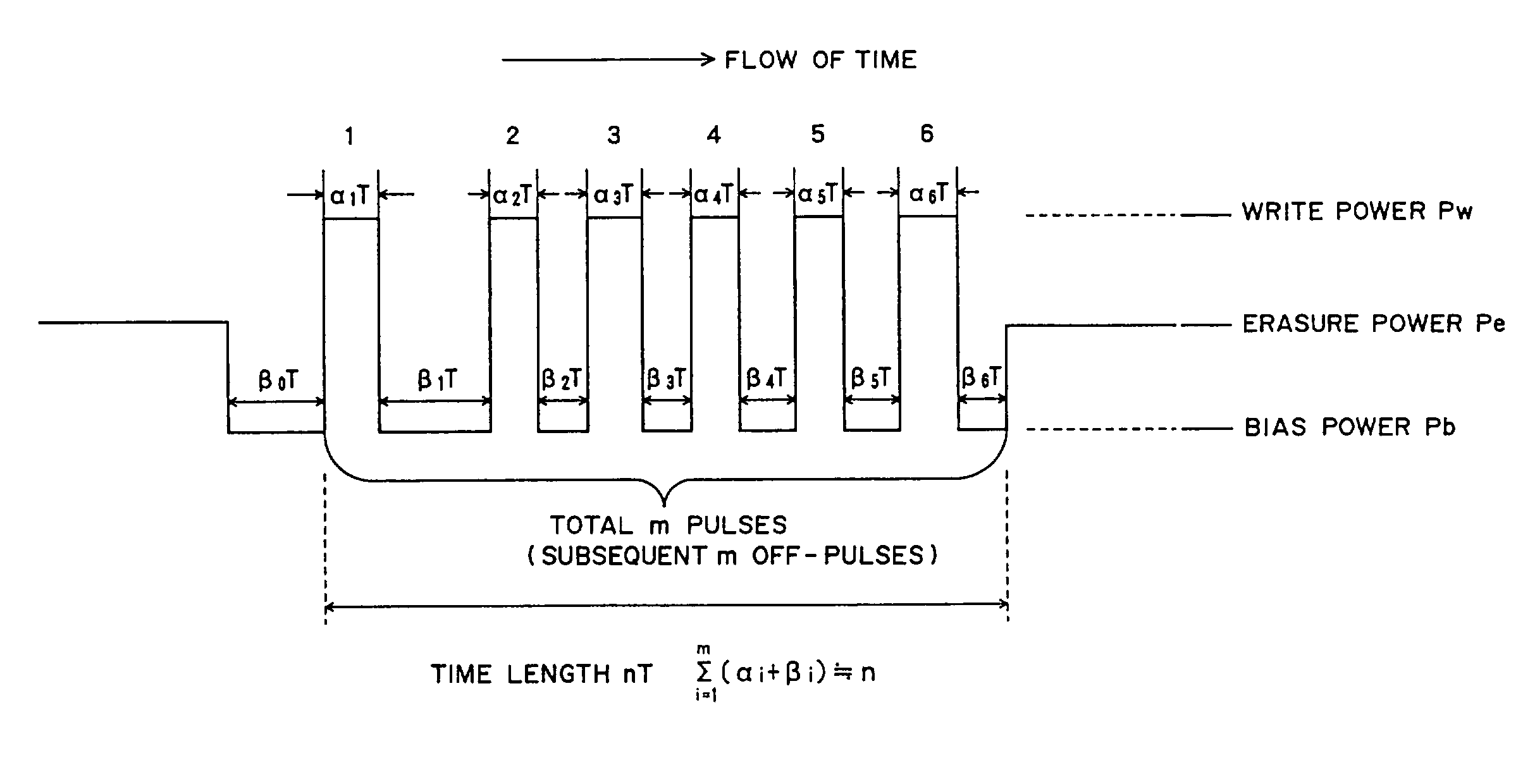
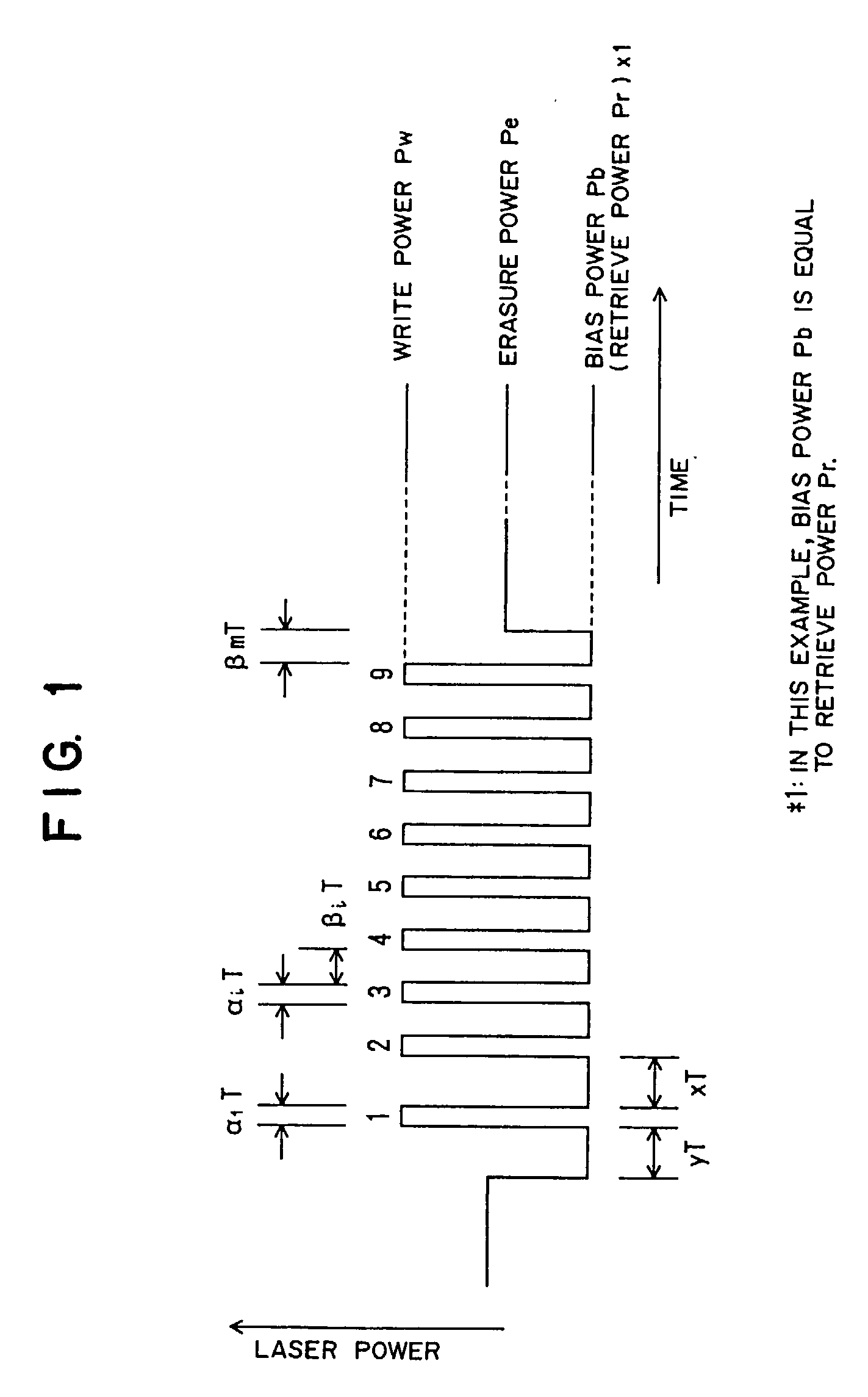
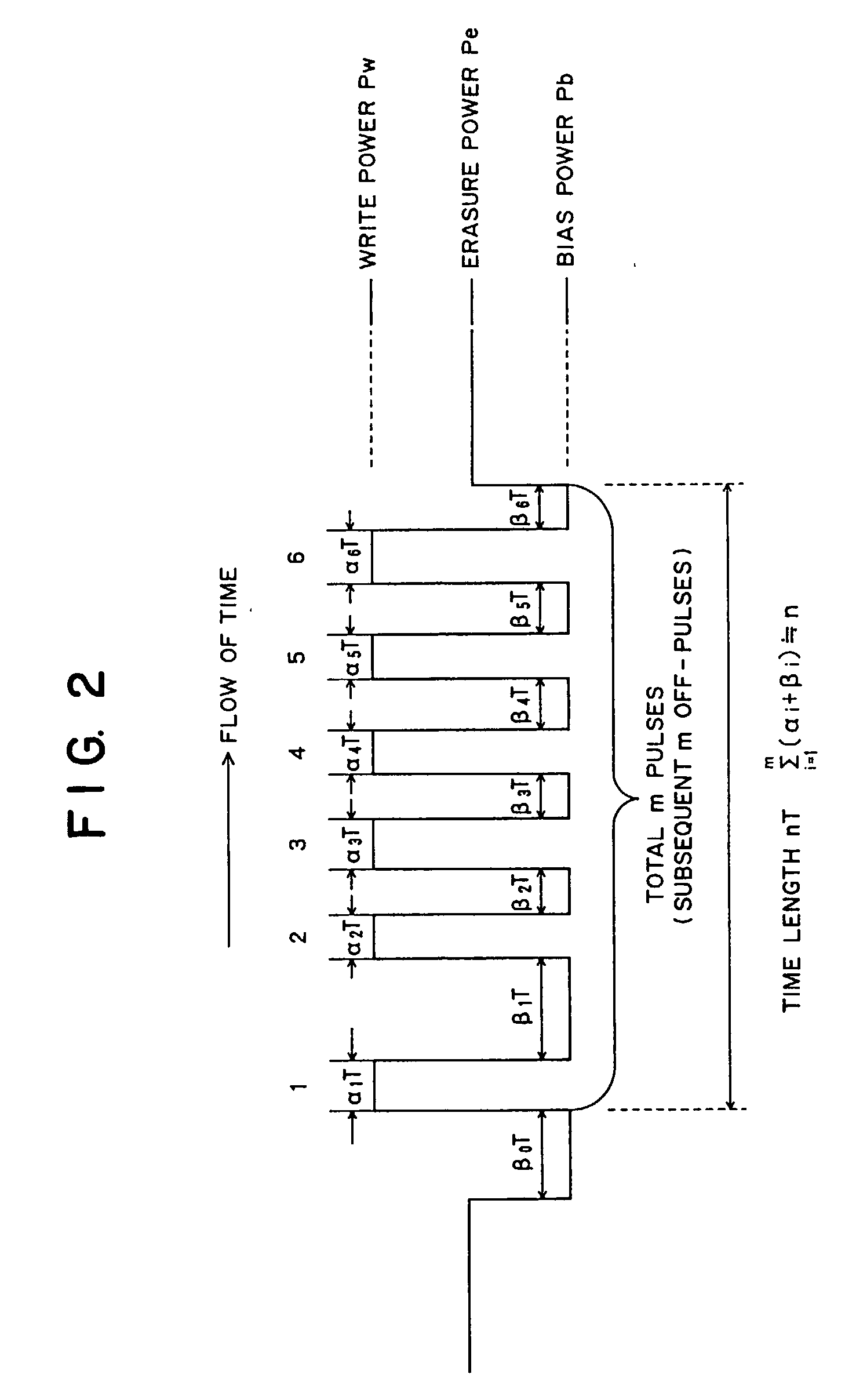
In a recording method for a rewritable optical recording medium, immediately before a prospective leading pulse that is a time section where recording light of write power Pw irradiates a phase-change recording layer for the first time as a front low-power energy irradiating step, light of bias power Pb irradiates the phase-change recording layer for a first set time length yT as a preceding low-power energy irradiation step. And immediately after the leading pulse, the light of bias power Pb irradiates the phase-change recording layer for a set time length xT as a succeeding low-power energy irradiation step. The relation between x and y satisfies: 0.95 <=x+0.7*y<=2.5. The high-power energybeam irradiates the recording medium in such a manner that a period of irradiation for pulses subsequent to the leading pulse is in a range of from 0.5T to 2.5T. The result is that it is possible to facilitate forming / erasing amorphous marks even in a phase-change recording medium devoid of a reflective layer, without any risk of narrowing the range of effective crystallization speeds.

Description

[0001] 1. Field of the Invention[0002] The present invention relates to a phase-change recording method suitable for recording on a phase-change recording medium, which can be in a multiplayer structure and is large in transmission factor (transmittance) like an optical disc enabling high-density recording, by utilizing a rewritable recording phase-change medium.[0003] 2. Description of Related Art[0004] Nowadays, as information amount growingly expands, demands for recording mediums which can record / retrieve a large capacity of data at high density and high speed have been on the rise. Therefore optical discs have been expected to meet these growing demands. Optical discs are divided into two types: one type enabling recording for only one time, and the other type enabling recoding / erasing for many times. The rewritable optical discs are exemplified by a magneto-optical recording medium utilizing a magneto-optical effect, and a phase-change medium utilizing change in reflectance wi...

Claims


Application Information

Patent Timeline
Patent Type & Authority Applications(United States)
IPC IPC(8): G11B7/00G11B7/0045G11B7/006G11B7/125G11B7/243
CPCG11B7/00454G11B7/006G11B7/0062G11B2007/24316G11B7/243G11B2007/0013G11B2007/24314G11B7/126
Inventor OHNO, TAKASHI
Owner CMC MAGNETICS CORPORATION
Why Eureka
Try Eureka