[0006] According to the present invention, the
combustion chamber passage orifice or the liquid passage or the outside contour is delimited in an adjacent edge area by a closed
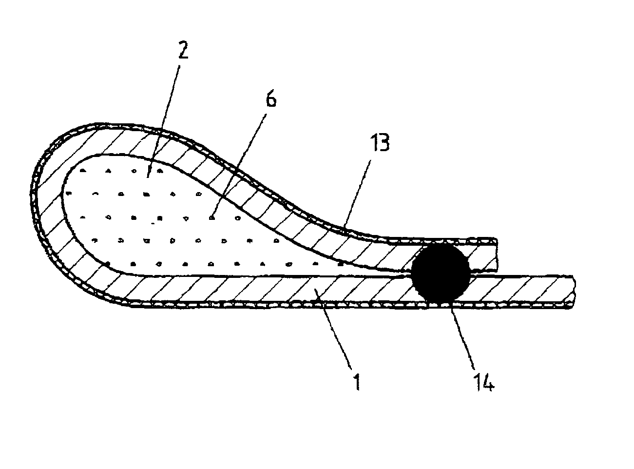
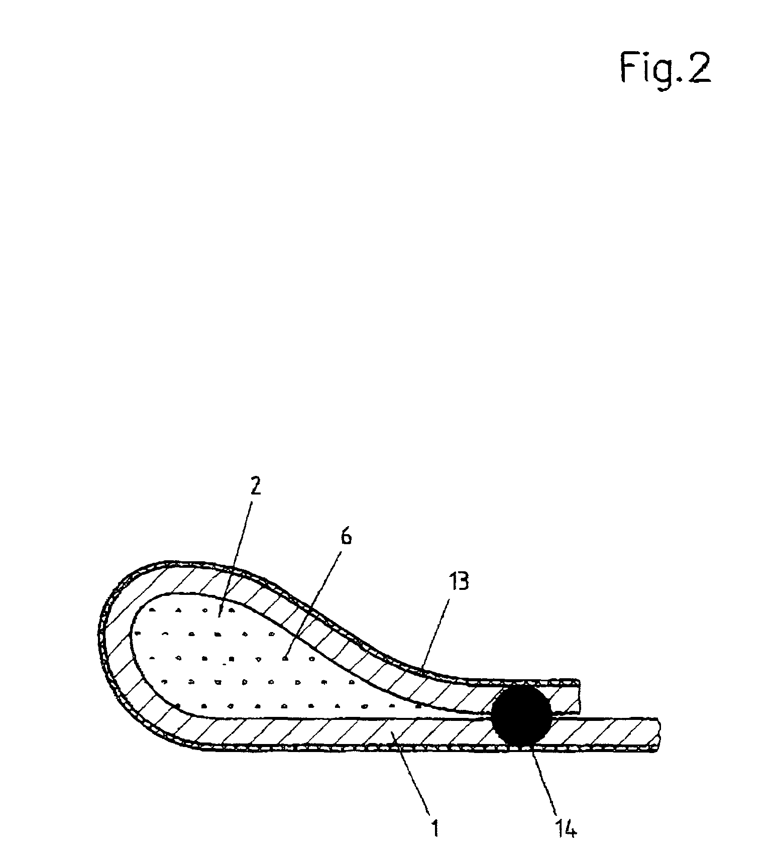
peripheral cavity of the gasket which is filled completely with a hydraulic medium. Due to the clamping force of the cylinder head screws, the flat gasket is pressed between the cylinder head and the
cylinder block, so that a constant
hydrostatic pressure develops in the cavity. The flexible tubular
enclosure surrounding the cavity then adapts to the unavoidable
distortion that occurs when clamping. The sealing contact with the sealing surfaces of the
cylinder block and the engine block is not lost even when the cylinder head and cylinder block execute both relative vertical and horizontal movements during operation of the
machine due to the ignition pressure. The hydraulic medium enclosed in the cavity causes a more uniform compressive sealing load over the circumference of the opening which is to be sealed. The elastic yielding behavior of the tubular
enclosure improves the sealing effect in the operating condition of the machine and increases the service life of the flat gasket.
[0008] It is preferable if the cavity is enclosed by at least one bead of the
metal sheet and a second
metal sheet bridging the bead, the two metal sheets being permanently joined together adjacent to the bead. In this construction, two laminated metal sheets are provided, one of which has a peripheral bead in the edge area of an orifice and the other bridges this bead. Permanent connection of the two metal sheets adjacent to the bead prevents a horizontal (as seen in the cross-sectional direction) yielding movement of the base of the bead under
compressive load. The distance between the legs at the base of the bead supporting the bead is thus essentially maintained, despite the compressive force in the sealing gap. The result of this is a high elastic resiliency of the bead. This resiliency guarantees that the contact between the flat gasket and the sealing surfaces of the engine block or the cylinder head producing the actual sealing effect will be maintained even with relatively large sealing gap movements.
[0009] It is advantageous if the cavity is filled completely with a
hydraulic fluid and the two metal sheets are joined in a fluid-tight manner. A high spring stiffness may be achieved, depending on the design of the bead. It is advantageous here if in the area of the bead the second metal sheet has a second bead which may have a design different from that of the first bead. Due to the differently designed beads, the flat gasket may be adapted very satisfactorily to the different materials of the cylinder head and the cylinder block with regard to frictional behavior. In cross section, the bead profile may have various shapes such as a U shape or a triangular shape. The sealing contact area of the flat gasket with the sealing surfaces of the cylinder head and cylinder block may thus be designed so that these sealing surfaces are not damaged due to pitting even after a lengthy
operating time. The metal sheets may be made of the same or different materials, such as
spring steel sheet of different thicknesses. It is of course also conceivable for other materials to be used, such as plastics instead of sheet metal. In a known manner, the gasket may be coated with an
elastomer layer in the sealing area. This elastomer film may be a rubber layer, for example, applied by spraying or
casting it onto the main sealing surfaces of the metal sheets. Due to the compressive forces in the sealing gap, this rubber layer is pressed into the
surface roughness of the respective sealing surfaces, thus achieving a micro-sealing effect.
[0010] It is preferable if a third metal sheet is arranged between the first metal sheet and the second metal sheet and this third metal sheet is included in the connection between the first and second metal sheets, the cavities on both sides of the third metal sheet being in
hydraulic connection with one another. This
hydraulic connection may be formed by a flow-through opening in the third metal sheet. This embodiment yields a flat gasket having a high rigidity which maintains sealing contact even with large relative movements of the cylinder head relative to the engine block.
[0011] It is especially preferable here if the third metal sheet in the area of the first and second beads has a third bead having a differently shaped profile. Depending on the design and embodiment of this third bead, the elastic resiliency of the flat gasket may be preselected within broad limits. The
hydraulic connection between the cavities prevents bulging of the third metal sheet enclosed between the two outer metal sheets. The flat gasket may be adapted very satisfactorily to the different materials used for the cylinder head and the cylinder block due to the beads which are designed with different cross sections. A round cross section or a bead composed of multiple partial beads increases the specific compressive loads per unit area with the adjacent sealing surface. The enlarged surface contact area with the sealing surface of the cylinder head prevents any digging into the surface. This is especially advantageous when the cylinder head is made of a
light metal alloy.

