
Ion trap mass spectrometer

a mass spectrometer and ion trap technology, applied in mass spectrometers, instruments, separation processes, etc., can solve the problems of deteriorating the sensitivity of the overall analysis, and the inability to obtain both at high levels, and achieve the effect of high analysis sensitivity and high levels

Inactive Publication Date: 2002-12-26
SHIMADZU CORP
View PDF1 Cites 16 Cited by
  • Summary
  • Abstract
  • Description
  • Claims
  • Application Information

AI Technical Summary

Benefits of technology

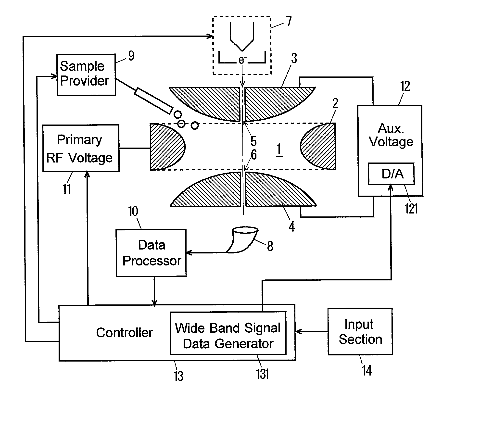
[0007] Thus an object of the present invention is to provide an ion trap mass spectrometer in which both the resolution of the mass-to-charge ratio and the sensitivity of the analysis are obtained at high levels in selecting ions in the ion trap space.
[0019] Owing to the ion trap mass spectrometer of the present invention, when object ions having a desired mass-to-charge ratio are to be selected and to be trapped in the ion trap space, the resonant vibration of the ions are adequately avoided. This assures more object ions left and trapped in the ion trap space. When an MS / MS analysis is subsequently conducted, for example, the number of object ions is maximized and so the sensitivity of the analysis is improved.

Problems solved by technology

When precursor ions are selected under the condition that the vibrating frequency is very high with a large amplitude of the primary RF voltage, however, a portion of the precursor ions to be selected is also discharged and less ions remain in the ion trap space, which deteriorates the sensitivity of the overall analysis.
That is, in the conventional methods as explained above, the resolution of the mass-to-charge ratio and the sensitivity of the analysis are in a trade-off, so that it was impossible to obtain both at high levels.

Method used


Image

  • Ion trap mass spectrometer
  • Ion trap mass spectrometer
  • Ion trap mass spectrometer

Examples


Embodiment Construction

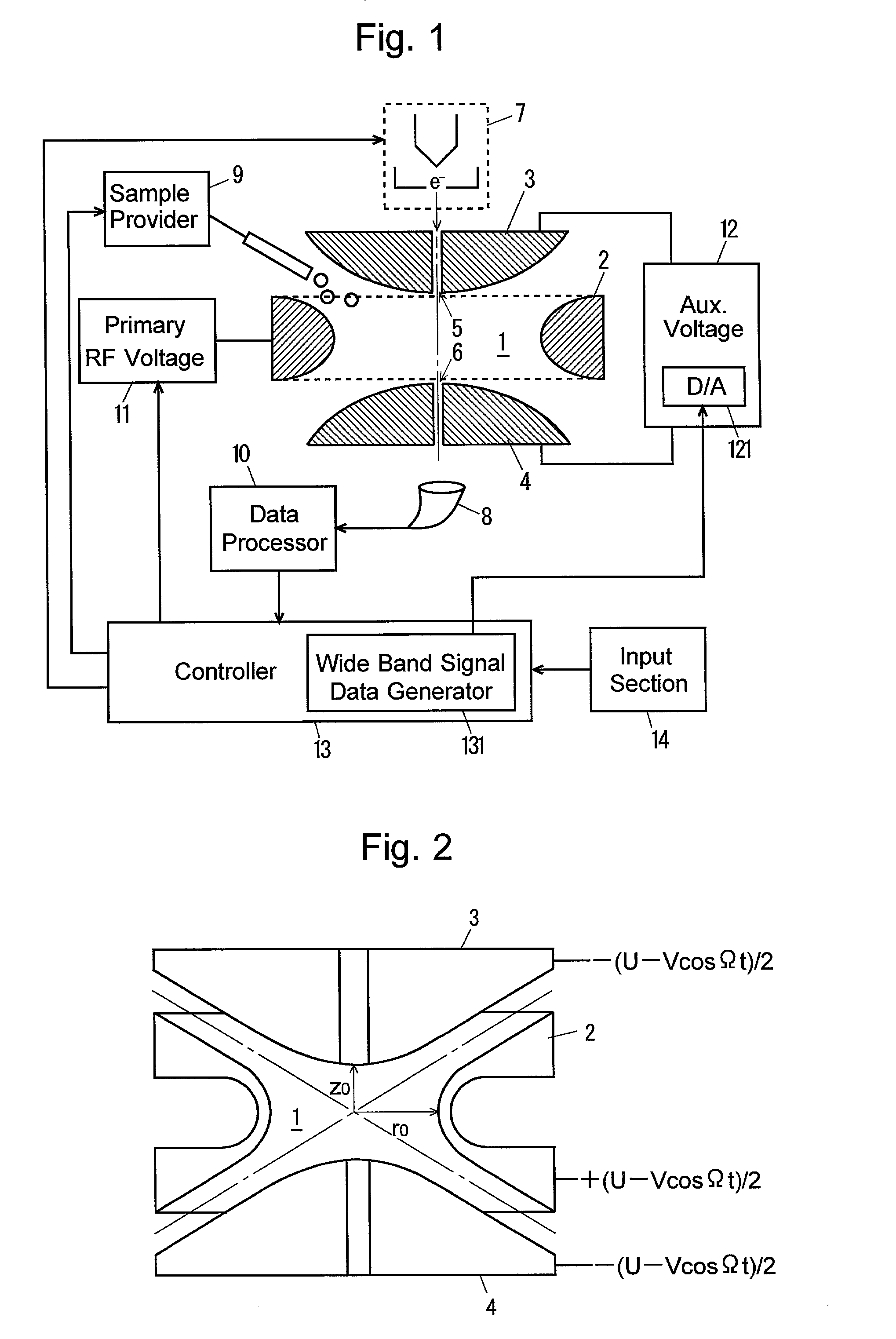
[0027] The principles of the ion selecting method according to the present invention is first described. FIG. 2 illustrates a typical ion trap mass spectrometer, in which a cylindrical coordinate system is defined with the z axis penetrating the center of the two end cap electrodes 3, 4.

[0028] The ion trap space 1 is defined by the space surrounded by the ring electrode 2 and the two end cap electrodes 3, 4 opposing each other with the ring electrode 2 between them. The ring electrode 2 has a hyperboloid-of-one-sheet-of-revolution internal surface, and the end cap electrodes 3, 4 have hyperboloid-of-two-sheets-of-revolution internal surfaces. A combination of a DC voltage and an RF voltage +(U-Vcos .OMEGA.t) / 2 is applied to the ring electrode 2 and another DC+RF voltage -(U-Vcos .OMEGA.t) / 2 is applied to the end cap electrodes 3, 4.

[0029] The vibration of the ions in the ion trap space 1 caused by the quadrupole electric field generated there by the voltages is described by the foll...


PUM


Abstract

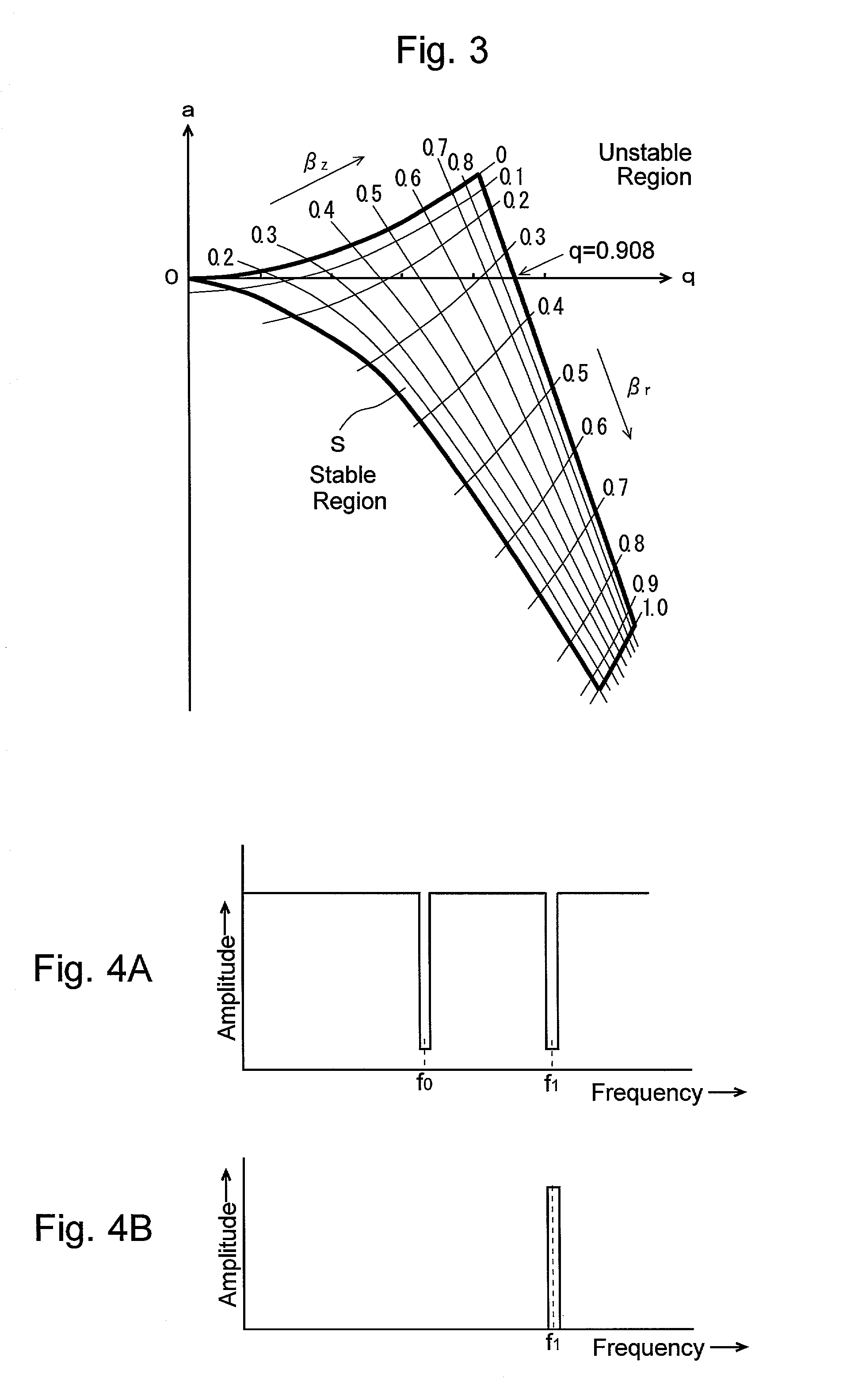
In an ion trap mass spectrometer including an ion trap space surrounded by a ring electrode and two end cap electrodes placed opposite each other with the ring electrode between them, a method of trapping object ions of a predetermined mass-to-charge ratio in the ion trap space more assuredly and effectively. The method includes the steps of: applying an RF voltage to the ring electrode to trap the object ions; and applying an auxiliary AC voltage to the end cap electrodes, where the auxiliary voltage has a frequency spectrum with a first notch at the basic frequency of the object ions and a second notch at a a beat frequency. Then the second stage is performed where another auxiliary AC voltage of the beat frequency is applied to the end cap electrodes to expel non-object ions still remaining in the ion trap space.

Description

[0001] The present invention relates to an ion trap mass spectrometer in which ions are trapped in the ion trap space with an appropriate electric field generated in it.[0002] An MS / MS analysis, or tandem analysis, is used with an ion trap mass spectrometer. In the MS / MS analysis, ions having a certain mass-to-charge ratio are selected from an analyzing sample as precursor ions. The selected precursor ions are dissociated with the Collision Induced Dissociation method, and the dissociated ions are mass-analyzed, whereby information on the mass and / or chemical structure of the object ions is obtained.[0003] In normal ion trap mass spectrometers, an ion trap space is formed surrounded by a ring electrode and two end cap electrodes placed opposite each other with the ring electrode between them. The ring electrode has a hyperboloid-of-one-sheet-of-revolution internal surface, and the end cap electrodes have hyperboloid-of-two-sheets-of-revolution internal surfaces. When appropriate vol...

Claims


Application Information

Patent Timeline
IPC IPC(8): H01J49/42G01N27/62
CPCH01J49/428H01J49/424
Inventor MISEKI, KOZO
Owner SHIMADZU CORP
Learn More