
Near-field exposure system selectively applying linearly polarized exposure light to exposure mask

a linear polarization, near-field exposure technology, applied in the direction of photomechanical equipment, instruments, printers, etc., can solve the problems of low throughput, low resolution limit of exposure light, and current electron beam lithographic techniques are far from the level which enables mass production

Inactive Publication Date: 2002-12-26
FUJIFILM HLDG CORP +1
View PDF0 Cites 11 Cited by
  • Summary
  • Abstract
  • Description
  • Claims
  • Application Information

AI Technical Summary

Problems solved by technology

However, in the lithography using light, the resolution limit is the diffraction limit of the exposure light.
However, because of low throughput and high cost, the current electron-beam lithographic techniques are far from the level which enables mass production.
However, it is not easy to realize the X-ray lithography since production of masks is not easy.
In addition, equipment cost is high.
However, when a polarizer is produced for each exposure mask as above, the exposure mask becomes expensive, and thus the cost of fine pattern exposure increases.

Method used


Image

  • Near-field exposure system selectively applying linearly polarized exposure light to exposure mask
  • Near-field exposure system selectively applying linearly polarized exposure light to exposure mask
  • Near-field exposure system selectively applying linearly polarized exposure light to exposure mask

Examples


first embodiment

Operations of First Embodiment

[0055] The operations of the near-field exposure system as the first embodiment of the present invention are explained below.

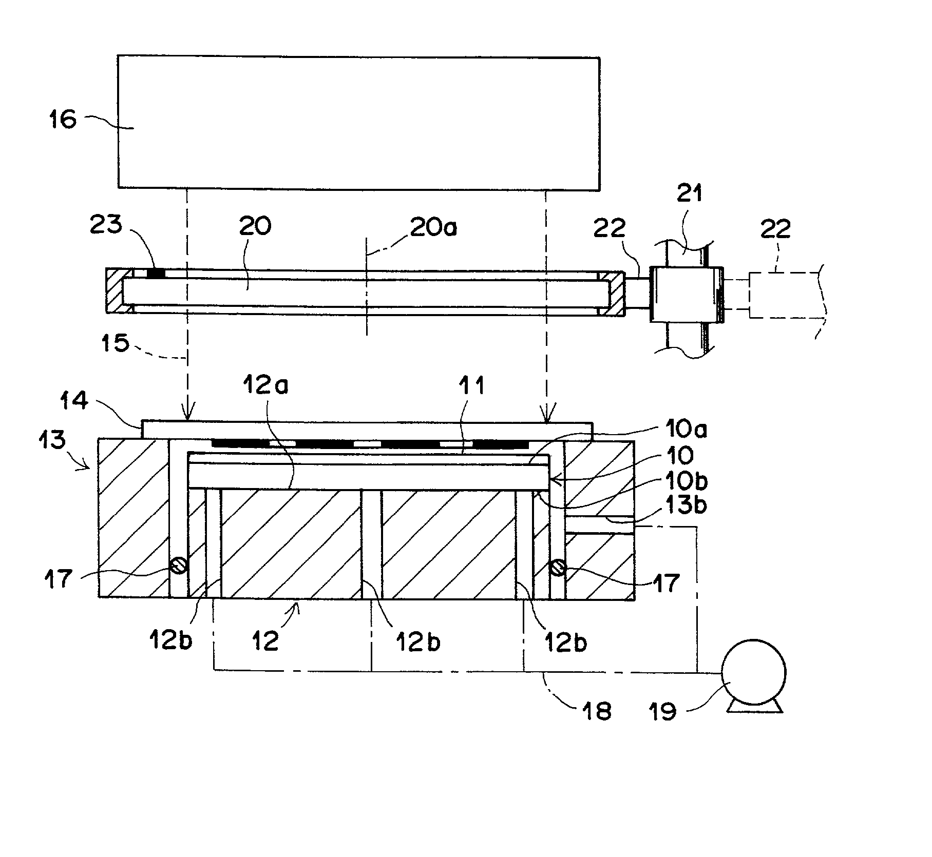
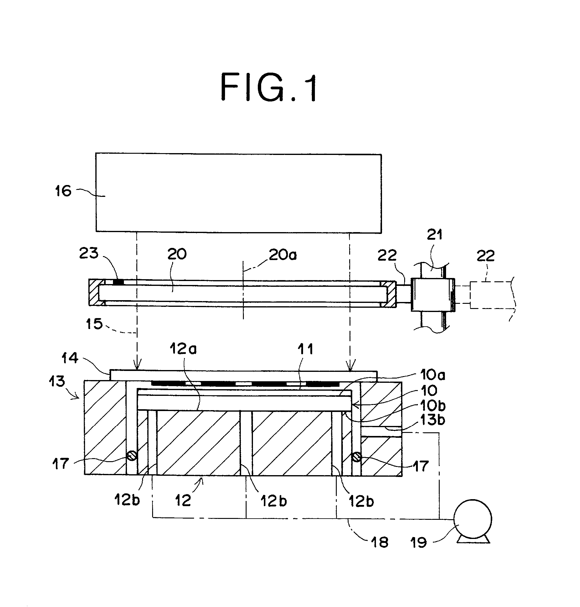
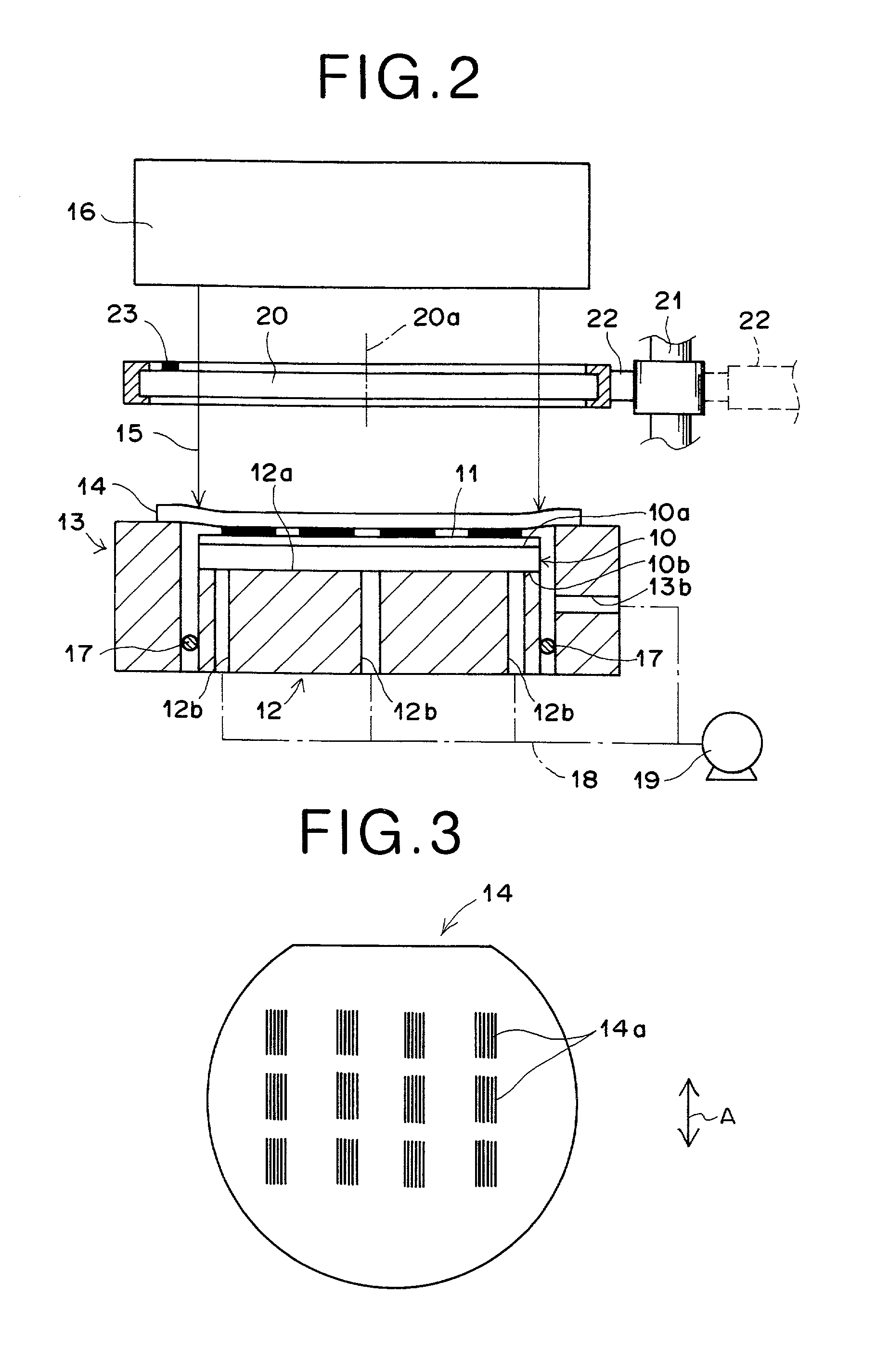
[0056] The substrate 10 is placed on the exposure table so that the back surface 10b of the substrate 10 is in contact with the substrate holding surface 12a, where the photoresist 11 is applied on the upper surface 10a of the substrate 10. In addition, the photomask 14 which has the aforementioned pattern is placed on the photomask holding member 13. At this time, the polarizer disk 20 is inserted in the optical path of the exposure light 15. This situation is illustrated in FIG. 1.

[0057] When the air suction means 19 is activated, air is sucked by the air suction means 19 from the plurality of ventilation paths 12b so that vacuum evacuation is achieved in the plurality of ventilation paths 12b, and the substrate 10 comes in contact with the substrate holding surface 12a of the exposure table 12 and is held by the exposure table ...

second embodiment

[0066] FIG. 4 is a side view, partly in cross section, of a near-field exposure system as the second embodiment of the present invention. In FIG. 4, elements having the same functions as the elements in the near-field exposure system illustrated in FIG. 1 bear the same reference numerals as FIG. 1, respectively, and only the differences from the construction of FIG. 1 are explained below.

[0067] The near-field exposure system as the second embodiment is essentially different from the first embodiment in that the exposure light source 36 emits linearly polarized exposure light 35, and a quarter-wavelength plate 30 (as a phase plate) is provided instead of the polarizer disk 20. For example, the exposure light 35 may be laser light.

[0068] The quarter-wavelength plate 30 can be inserted in the optical path of the exposure light 35 from the exposure light source 36 to the photomask 14. Specifically, the quarter-wavelength plate 30 is held by a polarizer-disk holding means 32, which can m...


PUM

PropertyMeasurementUnit
wavelengthaaaaaaaaaa

Abstract

In a near-field exposure system: a light source emits exposure light having a predetermined wavelength and being unpolarized; a polarizer plate linearly polarizes the exposure light; an exposure mask which has a pattern of openings each having a dimension smaller than the wavelength of the exposure light is placed at such a position that the exposure light is applied to the exposure mask; an exposure table holds a photosensitive material sensitive to the exposure light, at a position which near-field light emerging from the openings reaches; and a polarizer-plate holding means holds the polarizer plate in such a manner that the polarizer plate can be moved between first and second positions, where the first position is in an optical path of the exposure light from the light source to the exposure mask, and the second position is outside the optical path.

Description

[0001] The subject matters disclosed in this specification are related to the subject matters disclosed in the copending, commonly-assigned U.S. patent application Ser. No. 09 / 562,076 filed by Masayuki Naya (the inventor of the present application) and Shinji Sakaguchi on May 1, 2000 and entitled "FINE PATTERN FORMING METHOD," corresponding to Japanese patent application No. 2000-119670, which is disclosed in Japanese Unexamined Patent Publication No. 2001-15427.[0002] The contents of the above copending, commonly-assigned U.S. patent application and the corresponding Japanese patent application are incorporated in this specification by reference.[0003] 1. Field of the Invention[0004] The present invention relates to a near-field exposure system which exposes a fine pattern on a photosensitive material such as a photoresist.[0005] 2. Description of the Related Art[0006] The development in the photolithographic technology has been supported by the development in the reduction-project...

Claims


Application Information

Patent Timeline
Patent Type & Authority Applications(United States)
IPC IPC(8): G03F7/20H01L21/027
CPCG03F7/70566G03F7/7035
Inventor NAYA, MASAYUKI
Owner FUJIFILM HLDG CORP
Learn More