
Assist features for contact hole mask patterns

a technology of mask pattern and support feature, which is applied in the direction of photomechanical equipment, photo-taking process, instruments, etc., can solve the problems of limited success, limited integration density and minimum feature size that can be achieved, and limited resolution enhancement techniques

Inactive Publication Date: 2003-01-09
GOOGLE LLC
View PDF0 Cites 11 Cited by
  • Summary
  • Abstract
  • Description
  • Claims
  • Application Information

AI Technical Summary

Benefits of technology

[0013] It is another object of the invention to provide a method of making a mask including assist features which are of reduced footprint and provide improved contact hole exposures.
[0014] It is a further object of the present invention to provide reduction of pattern data and lithographic writing time in reticle manufacture.

Problems solved by technology

Therefore, lithographic resolution of a given exposure tool generally limits the integration density and minimum feature size that can be achieved.
However, known resolution enhancement techniques are only applicable to singular small features such as contact holes to allow scaling of contacts as the devices themselves are scaled to smaller sizes with substantial difficulty in reticle formation and with limited success.
More specifically, attempts to provide assist features have presented several problems.
While such reduced sizes are possible through demagnification of the mask pattern during lithographic exposures (except for the use of X-rays where a contact mask must be employed), formation of assist features of ideal size and placement in a mask may compromise reliability of manufacture of the mask, itself, leading to a likelihood of increased costs due to loss of mask manufacturing yield.
Perhaps more importantly, approaches using numerous discrete assist features, such as an array of mask apertures to create a contact hole, that have been employed, provide resolution of images which is of less than desired quality since resolution increases with the number of assist features but the number of assist features is generally limited by practical considerations.
For example, the number of assist features which must be separately written to the mask greatly increases mask pattern writing time and thus increases mask costs.
Further, the data involved may approach or exceed mask writer capacity.
Moreover, the area required for such assist features may also exceed the area that can be accommodated in masks for devices having very high integration density since features that may not be substantially nested may still be sufficiently proximate that the areas ideally required for SRAF structures may overlap or interact.
Thus, assist features comprising arrays of mask apertures can only be used to form a contact hole where the contact hole is isolated from other features.
Accordingly, the use of conventional assist features for production of contact holes may severely complicate integrated circuit layout and is not applicable to the majority of circumstances where contact holes are needed (e.g. to contact different parts of, for example, a transistor of small dimensions).

Method used


Image

  • Assist features for contact hole mask patterns
  • Assist features for contact hole mask patterns

Examples


Embodiment Construction

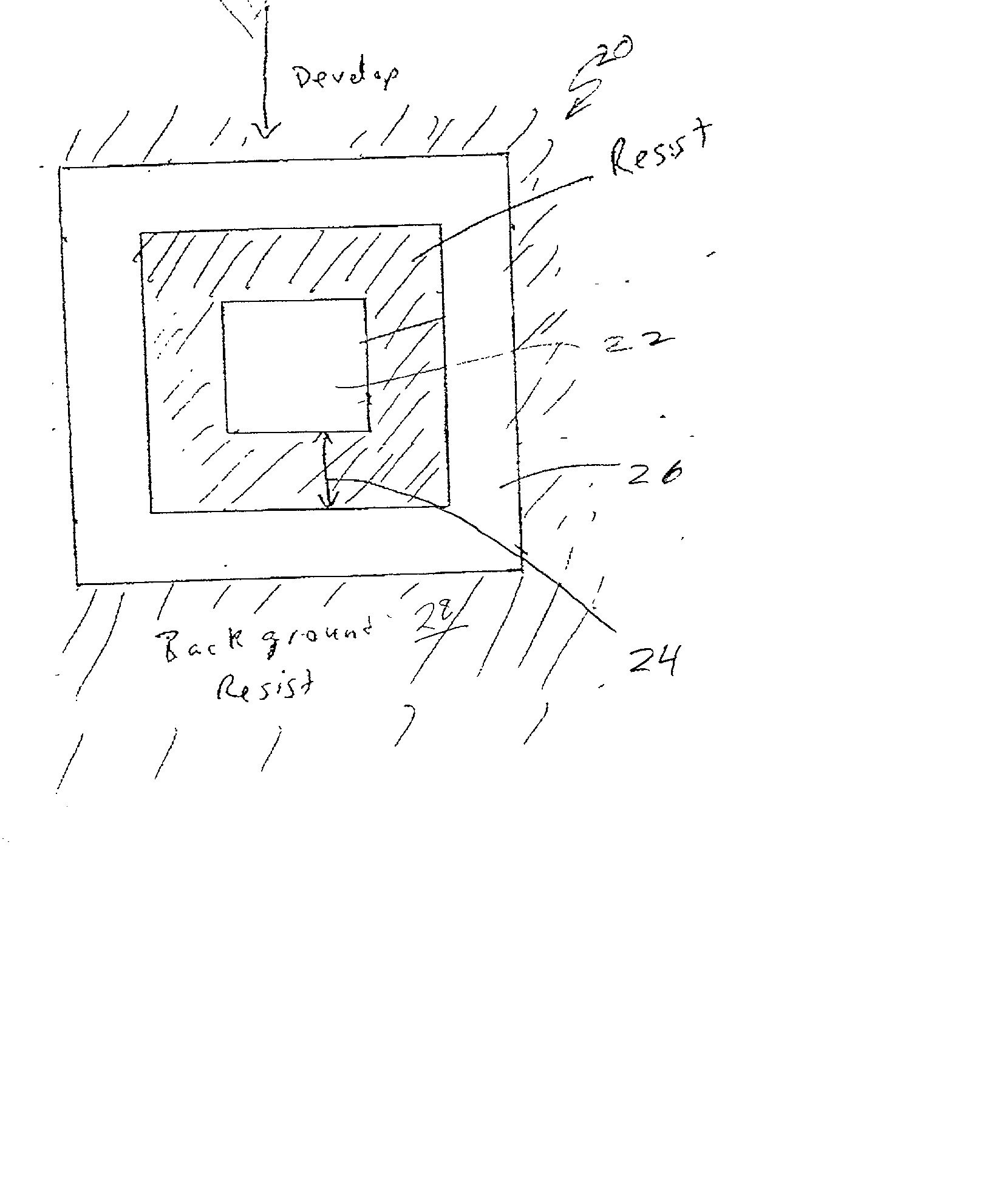
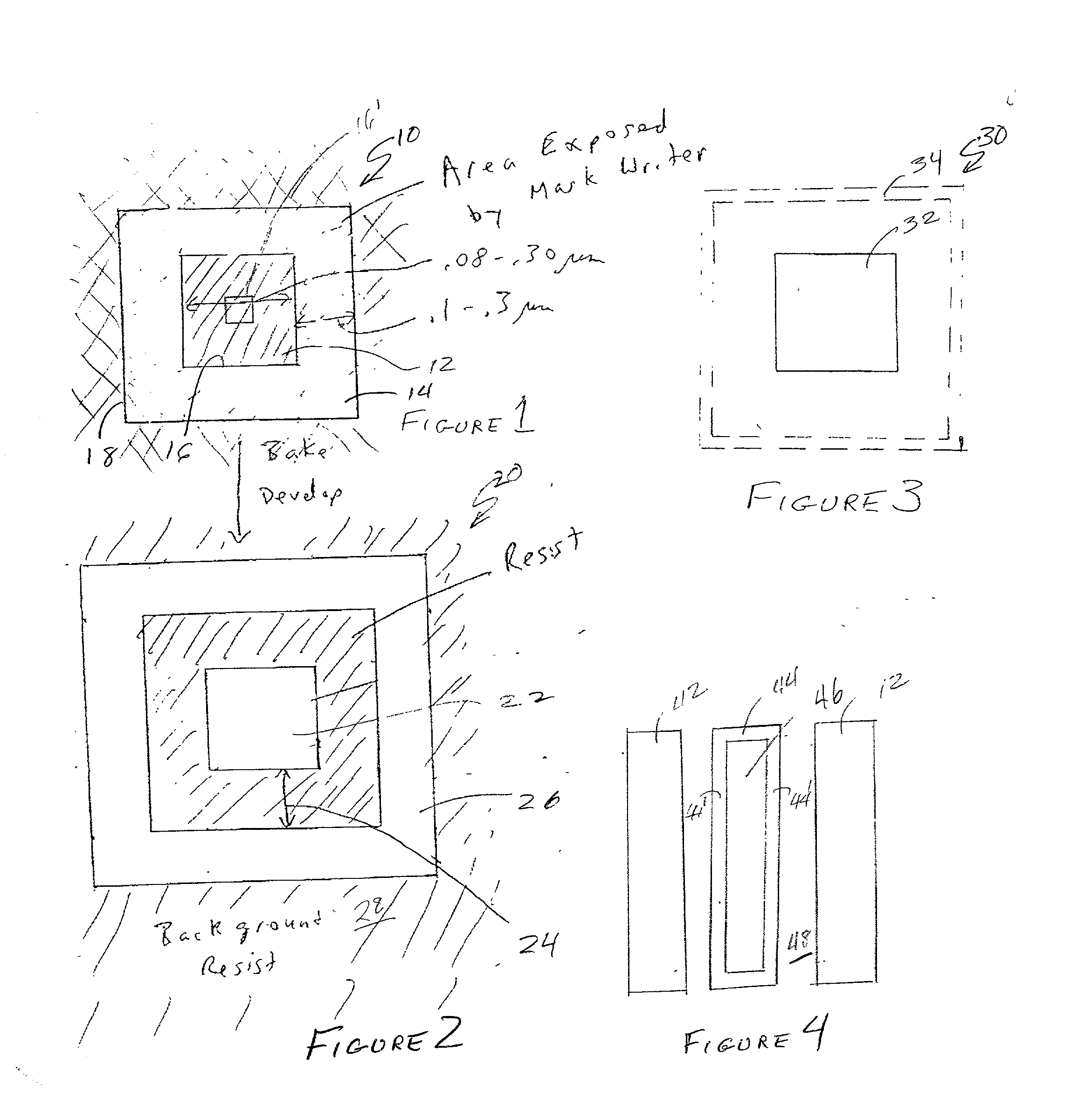
[0023] Referring now to the drawings, and more particularly to FIG. 1, there is shown, in plan view, an exemplary pattern 10 for exposure of a resist on a mask substrate for lithographic production of a contact hole with a further exposure of a resist layer using the mask. While a square shaped feature is somewhat preferred and thus illustrated in FIG. 1 for clarity and simplicity of production using available mask writing tools, the particular shape is not important to the successful practice of the invention in accordance with its basic principles.

[0024] It should be understood that the pattern 10 of FIG. 1 is intended for exposure of a hybrid resist such as that disclosed in detail in U. S. Pat. 6,114,082 to Hakey et al. assigned to the assignee of the present invention and hereby fully incorporated by reference. In essence, a hybrid resist, as disclosed therein, includes both positive and negative resist materials providing positive and negative tone responses, respectively. By ...


PUM


Abstract

An assist feature is formed on a lithographic reticle or mask using a hybrid resist and an exposure dose such that only an annular area is effectively exposed having a width that is potentially less than the minimum feature size that can be resolved by the mask exposure tool to simultaneously or sequentially form both a feature of interest and an assist feature for enhancing imaging of the feature of interest when the feature is printed to a wafer. Since the assist feature can be imaged simultaneously with the feature of interest or multiple assist features imaged concurrently, possibly between closely spaced features, data volume and mask writing time are greatly reduced. The invention is particularly applicable to the scaling of contact holes for connections to active devices in extremely high density integrated circuits.

Description

[0001] 1. Field of the Invention[0002] The present invention generally relates to lithographic processes for manufacture of semiconductor integrated circuits and, more particularly, to production of assist features on lithographic reticles and masks.[0003] 2. Description of the Prior Art[0004] The potential for improved performance and functionality of integrated circuits as well as potentially increased manufacturing economy has led to designs utilizing extremely small feature size regimes and much increased integration density. While numerous advances in semiconductor technology have allowed electronic devices to be fabricated at smaller sizes and in increased numbers and proximity on a chip while maintaining electrical characteristics, many gains in integration density have been achieved through scaling of existing device designs to smaller sizes, implying reduced dimensions of components of devices (e.g. gate insulator thicknesses and channel lengths and widths), operation at lo...

Claims


Application Information

Patent Timeline
IPC IPC(8): G03F1/00G03F7/095
CPCG03F1/144G03F7/095G03F1/36
Inventor BULA, ORESTHIBBS, MICHAEL S.HOLMES, STEVEN J.RABIDOUX, PAUL A.
Owner GOOGLE LLC
Learn More