
Electrical therapy device

a technology of electric therapy and electrodes, applied in the field of electric therapy devices, can solve problems such as patients' occasional fainting attacks

Inactive Publication Date: 2003-01-09
BIOTRONIK MESS UND THERAPIEGERAETE GMBH & CO
View PDF13 Cites 8 Cited by
  • Summary
  • Abstract
  • Description
  • Claims
  • Application Information

AI Technical Summary

Benefits of technology

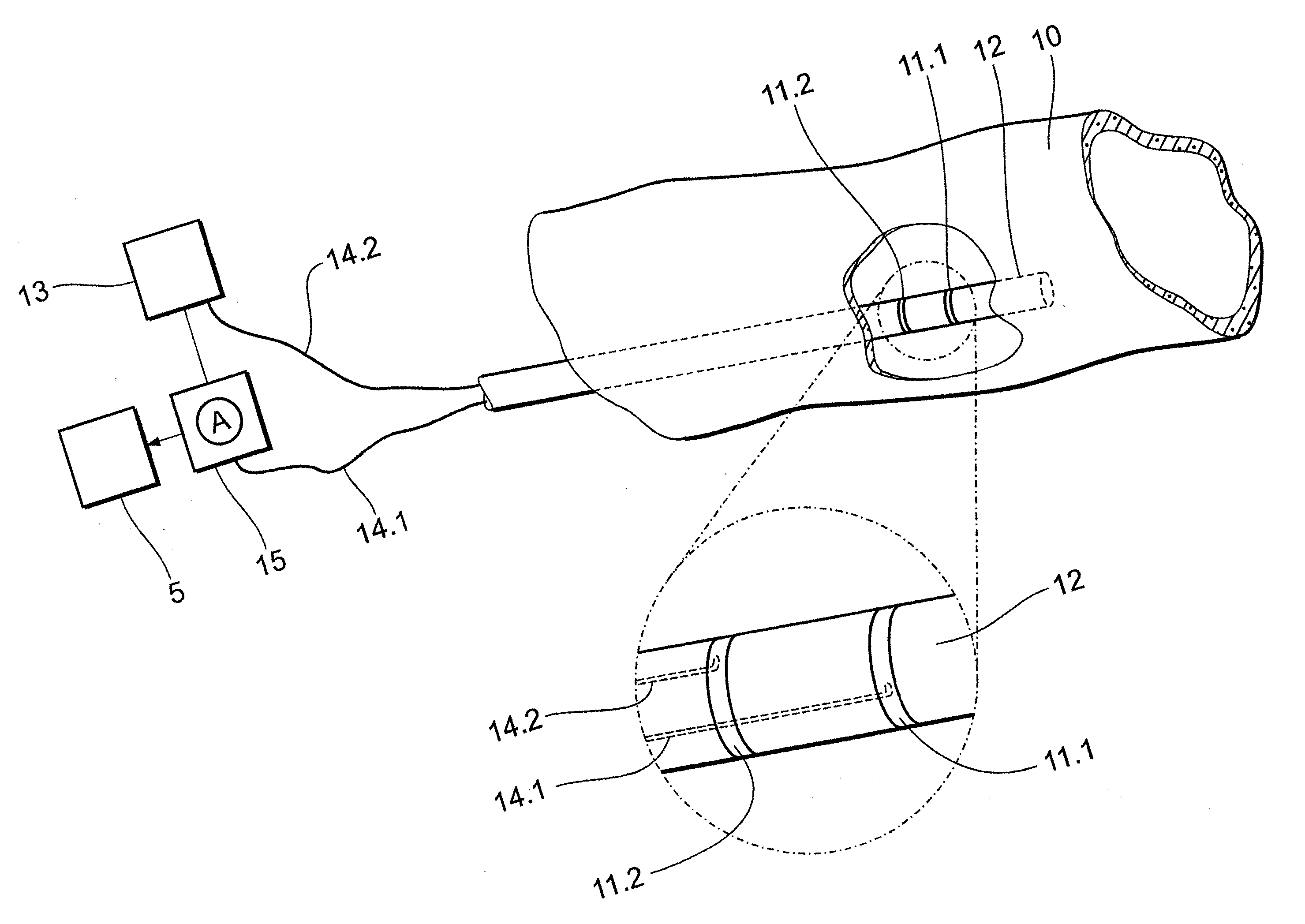
[0015] It has been found to be further advantageous that not just the peripheral effects of a tachyarrhythmia but also the peripheral vasomotor influence is also detected by the peripheral hemodynamic sensor.
[0016] Therefore the advantages achieved by the invention are in particular that the negative effects of temporary tachyarrhythmias of low degree, such as for example an undersupply of oxygen, on the patient are reduced so that deficiency symptoms in the peripheral organs can be avoided or reduced.
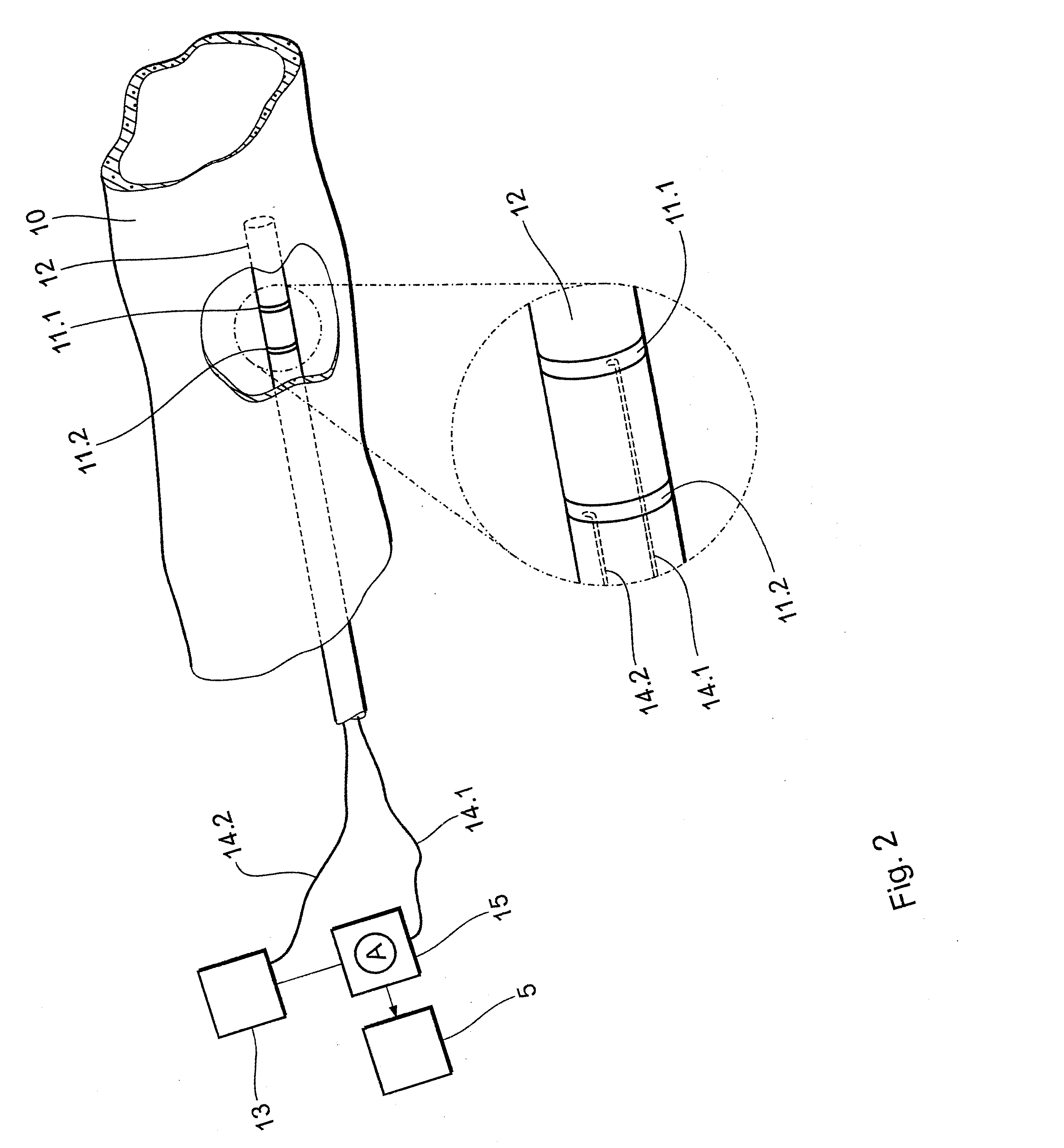
[0018] Impedance measurement in respect of the peripheral blood therefore represents a simple way of determining the peripheral blood flow which is used in turn to determine the negative effects of tachyarrhythmias on the peripheral hemodynamics.
[0025] In a further preferred configuration of the invention the hemodynamic sensor is arranged in the region of the carotid sinus. In that way it is possible to detect and avoid in particular a deficient supply to the brain.

Problems solved by technology

In contrast to a merely physiological increased heart rate as for example in the case of a hemodynamically stable tachycardia tachyarrhythmias represent a problem in terms of the oxygen supply to the body by the cardiovascular system as they can have a negative influence on the blood and oxygen supply.
It has been found however that some patients occasionally suffer from fainting attacks in spite of being provided with known electrical therapy devices.

Method used


Image

  • Electrical therapy device
  • Electrical therapy device
  • Electrical therapy device

Examples


Embodiment Construction

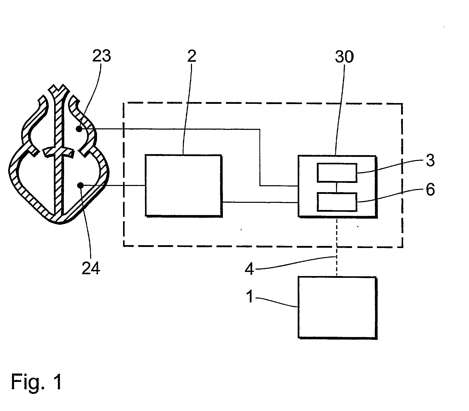
[0030] FIG. 1 shows a schematic block circuit diagram of an electrical therapy device. In this case the electrical therapy device comprises a hemodynamic sensor 1, an electrostimulation device 2 and a control unit 30. Both the hemodynamic sensor 1 and also the control unit 30 are adapted to communicate wirelessly with each other, at 4. In this arrangement the control unit 30 has a detection unit 9 (see FIG. 3) which is adapted to analyse a signal originating from the hemodynamic sensor 1, in such a way that an output signal of the detection unit depends on the detection of hemodynamic undersupply as detected by the hemodynamic sensor 1. The therapy device also has a telemetry receiver 6. The electrostimulation device 2 is connected by way of an electrode line to an intracardiac electrode 24 which is used for stimulating and defibrillating the heart. The detection unit 9 is preferably part of an evaluation device 3 which is particularly preferably in the form of a tachyarrhythmia eva...


PUM


Abstract

An electrical therapy device for a heart has a hemodynamic sensor (1), an electrostimulation device (2) and a control unit (30). The hemodynamic sensor (1) is adapted to detect a peripheral blood flow. In this arrangement, the control unit (30) has a tachyarrhythmia evaluation device (3) and a telemetry receiver (6). The control unit (30) controls the electrostimulation device (2) for stimulating and defibrillating the heart in dependence on the peripheral blood flow which is detected by the hemodynamic sensor (1). In addition a tachyarrhythmia and / or the peripheral hemodynamic effects thereof is detected, wherein the peripheral hemodynamic effects of the tachyarrhythmia are determined on the basis of the peripheral blood flow which is detected by a peripheral hemodynamic sensor (1). The results of detecting a tachyarrhythmia and / or the peripheral hemodynamic effects thereof can be used to defibrillate or stimulate the heart by means of the electrostimulation device (2).

Description

ELECTRICAL THERAPY DEVICE[0001] The present invention relates to an electrical therapy device for a heart, comprising an electrostimulation device which is adapted to stimulate the heart, a hemodynamic sensor which is adapted to detect a peripheral blood flow, and a control unit which is adapted to control the electrostimulation device in dependence on the peripheral blood flow detected by the hemodynamic sensor.BACKGROUND OF THE ART[0002] The aim of a therapy device of that kind is to regulate the cardiovascular capacity and to supply the body with an adequate amount of oxygen-enriched blood. The cardiac delivery capacity or cardiac output and the amount of blood which is pumped out of the heart per unit of time represent parameters of fundamental interest in the case of implantable electrical therapy devices such as for example cardiac pacemakers and defibrillators. Those parameters represent good indices in regard to determining an adequate blood supply.[0003] If accurate measure...

Claims


Application Information

Patent Timeline
Patent Type & Authority Applications(United States)
IPC IPC(8): A61N1/365A61N1/39
CPCA61N1/36521A61N1/36528A61N1/36557A61N1/36564A61N1/36571A61N1/3962A61N1/39622
Inventor REINKE, HEINRICHMUESSIG, DIRKSCHALDACH, MAXSCHALDACH, MAX JR.
Owner BIOTRONIK MESS UND THERAPIEGERAETE GMBH & CO
Learn More