Method and device for the control of a fuel injection valve

a fuel injection valve and solenoid technology, applied in the direction of electric control, machines/engines, instruments, etc., can solve the problems of insufficient pull-up current for solenoid injection valves, inability to ensure reliable opening of solenoid valves, and long booster phase producing this high current level over the entire pull-up phase. achieve the effect of improving the switch-on performance and maximizing the booster energy

Inactive Publication Date: 2003-01-16
ROBERT BOSCH GMBH
View PDF5 Cites 39 Cited by
  • Summary
  • Abstract
  • Description
  • Claims
  • Application Information

AI Technical Summary

Benefits of technology

[0007] In view of the disadvantages of the related art described above, the general objective of the invention is to utilize the booster energy economically and, in addition, to improve the switch-on performance of the valve, even given a small battery voltage.[0008] According to one essential aspect of the invention, this objective is achieved by activating a plurality of booster pulses in succession during the triggering phase of the solenoid valve. In principle, their time position within the triggering phase is freely selectable.[0009] Thus, in a first exemplary embodiment of the present invention, after the first booster pulse is activated at the beginning of the pull-up phase, a further booster pulse can be activated still prior to or during the flight phase of the valve needle.[0010] According to a second exemplary embodiment, after the first booster pulse is activated at the beginning of the pull-up phase, a further booster pulse can be activated at the end or immediately after the flight phase of the valve needle.[0011] Finally, according to a third exemplary embodiment, a further booster pulse or a plurality of further booster pulses can be activated during the holding phase of the solenoid valve, if the voltage of the supply battery lies below a specific threshold voltage during this holding phase.[0012] The exemplary embodiments of the present invention described above can also be combined with one another.[0013] The energy or the maximum current of the individual booster pulses can be reduced by the repeated boosting compared to one long single boosting with a very high current intensity. A reduced peak current intensity brings with it a lower load of the bonding pads for integrated circuits, of hybrid assemblies, and a smaller storage capacitance of the booster capacitor.[0014] By suitable selection of the moments for the second and possibly third booster pulse, the buildup of the magnetic force can be freely varied timewise. This leads to a decrease in the eddy-current formation, and the booster energy can be supplied depending on the need of the solenoid valve as a function of time. In this manner, the pull-away of the valve needle of the solenoid valve from the lower limit-stop point can be supported, the needle flight can be accelerated, and stop bounces at the upper limit stop of the valve needle can be suppressed.[0015] Furthermore, given too low a battery voltage which does not suffice to drive a sufficiently high current through the high-pressure injector, the current level can nevertheless be raised by the multiple boosting, and thus reliable operation of the high-pressure solenoid injection valve can be ensured.

Problems solved by technology

Thus, particularly at low battery voltage accompanied by a given ohmic resistance in the circuit, sufficient pull-up current for the solenoid injection valve cannot be built up.
That is to say, (I
Because of the high withdrawal of energy from the internal booster capacitor, a theoretically conceivable, long booster phase producing this high current level over the entire pull-up phase is not sensible.
This means a poor dynamic response of the solenoid valve.

Method used


Image

  • Method and device for the control of a fuel injection valve
  • Method and device for the control of a fuel injection valve
  • Method and device for the control of a fuel injection valve

Examples


Embodiment Construction

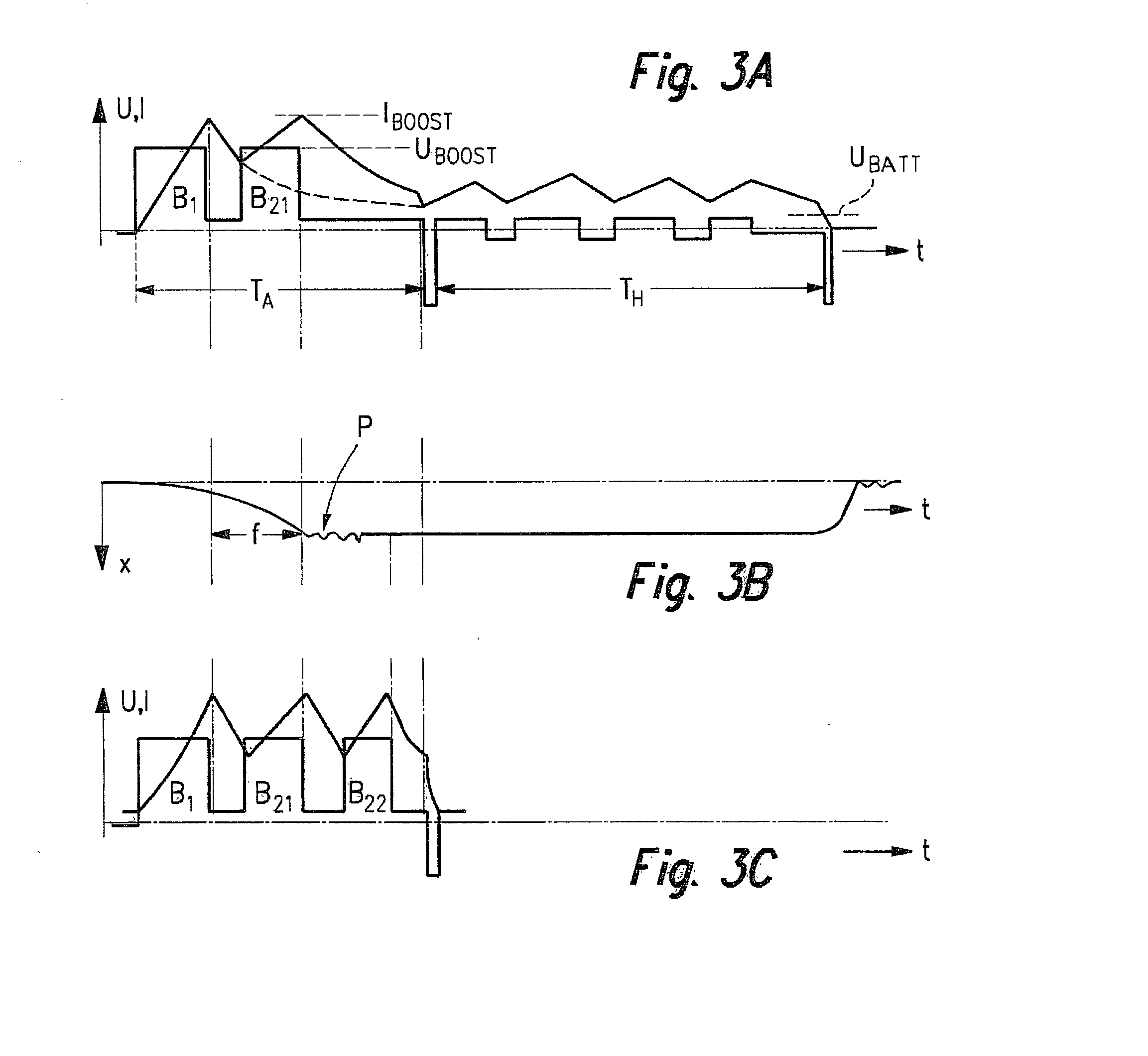
[0022] The graphic representation in FIG. 3a shows a first exemplary embodiment of the method according to the present invention in which, given a relatively low battery voltage U.sub.BATT, a double boosting takes place. That is to say, after first booster pulse B.sub.1 is activated at the beginning of pull-up phase T.sub.A, a further booster pulse B.sub.21 is activated which, as a comparison with FIG. 3B showing excursion X of the valve needle immediately makes clear, takes place during flight phase f of the valve needle. The drop of the current through the magnetic coil, indicated by a dotted line in FIG. 3A, is thereby avoided, so that the regulating range of the pull-up current regulation is reached in spite of low battery voltage U.sub.BATT, and reliable opening of the valve is ensured. Thus, even given low battery voltage U.sub.BATT, the current level can be held up during pull-up phase T.sub.A by the double boosting, and the valve can thereby be reliably opened.

[0023] FIG. 3C...


PUM


Abstract

The present invention relates to a method and a device for triggering a solenoid valve for injecting fuel into an internal combustion engine, the triggering phase of the solenoid valve being subdivided into a pull-up phase (TA), during which a valve needle of the solenoid valve is caused to open by a first current intensity (IA) flowing through a magnetic coil of the solenoid valve, and into a holding phase (TH) during which the valve needle is held in the open state by a second, lower current intensity (IH) flowing through the magnetic coil, and at least once at the beginning of the pull-up phase (TA), a booster phase (B1) being activated during which a pulse-shaped booster current (IBOOST) from a booster capacitor charged to a high voltage (UBOOST) flows through the magnetic coil; and is characterized in that during the triggering phase of the solenoid valve, a plurality of booster pulses (B1, B21, B22) are activated in succession, whose time position within the triggering phase is freely selectable (FIGS. 3A-3C).

Description

BACKGROUND INFORMATION[0001] The present invention relates to a method and a device for triggering a solenoid valve, particularly for injecting fuel into an internal combustion engine, the triggering phase of the solenoid valve being subdivided into a pull-up phase, during which a valve needle of the solenoid valve is caused to open by a first current intensity flowing through a magnetic coil of the solenoid valve, and into a holding phase during which the valve needle is held in the open state by a second, lower current intensity flowing through the magnetic coil, and at least once at the beginning of the pull-up phase, a booster phase being activated during which a pulse-shaped booster current from a booster capacitor charged to a high voltage or from another current source flows through the magnetic coil.[0002] Such a method and such a device are known from the German patent 197 46 980 A1 of Robert Bosch GmbH.[0003] The attached FIGS. 1 and 2 show, in the form of signal diagrams,...

Claims


Application Information

Patent Timeline
Patent Type & Authority Applications(United States)
IPC IPC(8): F02M51/00F02D41/02F02D41/20F02M51/06F02M65/00
CPCF02D41/20F02D2041/2003F02D2041/2006F02D2041/2013
Inventor REISCHL, ROLFEICHENDORF, ANDREASPISCHKE, ULFECKHARDT, JUERGENMUELLER, KLAUS
Owner ROBERT BOSCH GMBH
Why Eureka
Try Eureka