Synchronous oscillators

a technology of synchronous oscillators and oscillators, which is applied in the direction of oscillator generators, digital transmission, pulse automatic control, etc., can solve the problems of noise rejection, inability to compensate for losses, and inability to match, so as to increase the bandwidth of the circuit, and improve the noise rejection sensitivity of the circuit

Inactive Publication Date: 2003-01-16
ANTHONY AESCHLIMANN
View PDF2 Cites 12 Cited by
  • Summary
  • Abstract
  • Description
  • Claims
  • Application Information

AI Technical Summary

Benefits of technology

0032] The bandwidth of the circuit may be increased;
0033] The input sensitivity of the circuit may be increased;
0034] The noise rejection sensitivity of the circuit may be improved;
0035] The frequency stability of the circuit may be increased; and
0036] The jitter rejection may be improved.
0094] The increase in any of the above may be up to about 30% or, in some cases, even greater.

Problems solved by technology

This is a result of the signal becoming so small that it cannot compensate for losses in the tank circuit.
However, compared to other circuits, a synchronous oscillator can provide a wide bandwidth, a high input sensitivity and a high noise rejection, which seems not to be matched by other circuits.

Method used


Image

  • Synchronous oscillators
  • Synchronous oscillators
  • Synchronous oscillators

Examples


second embodiment

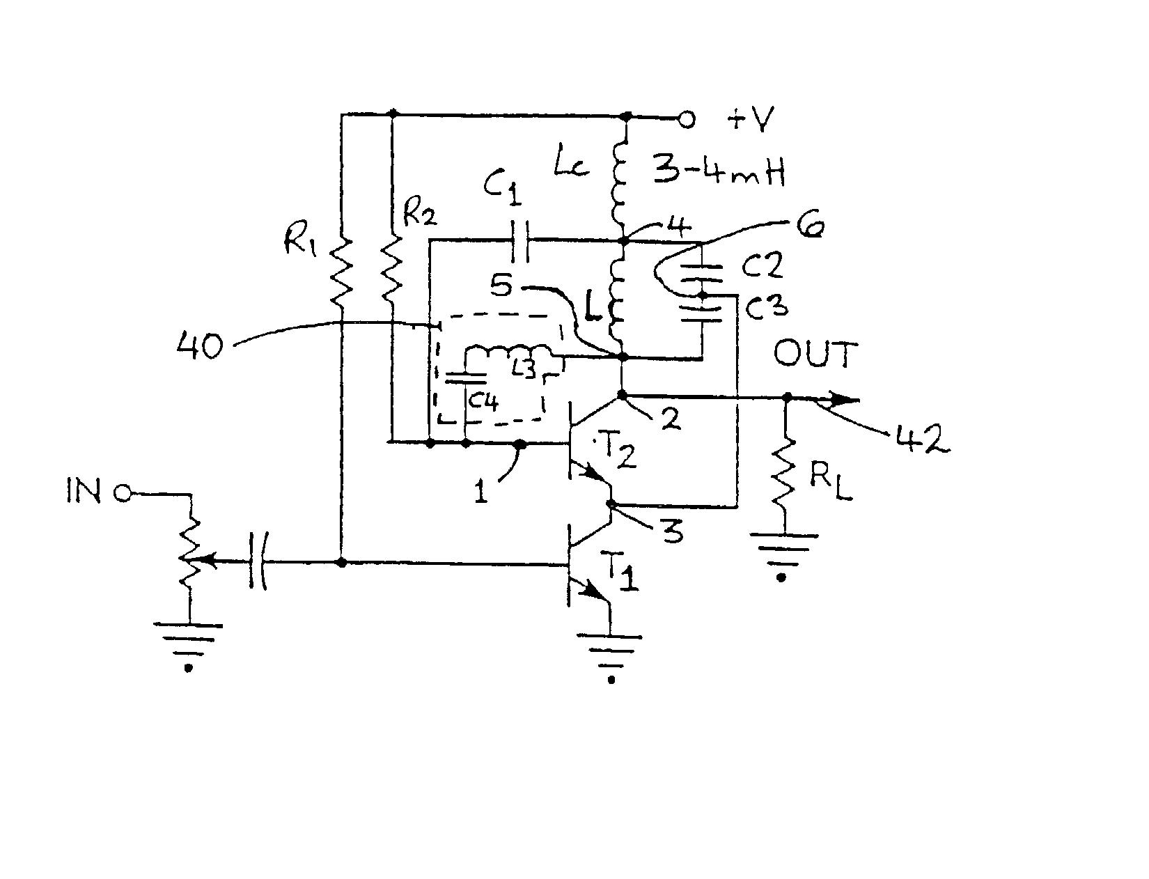
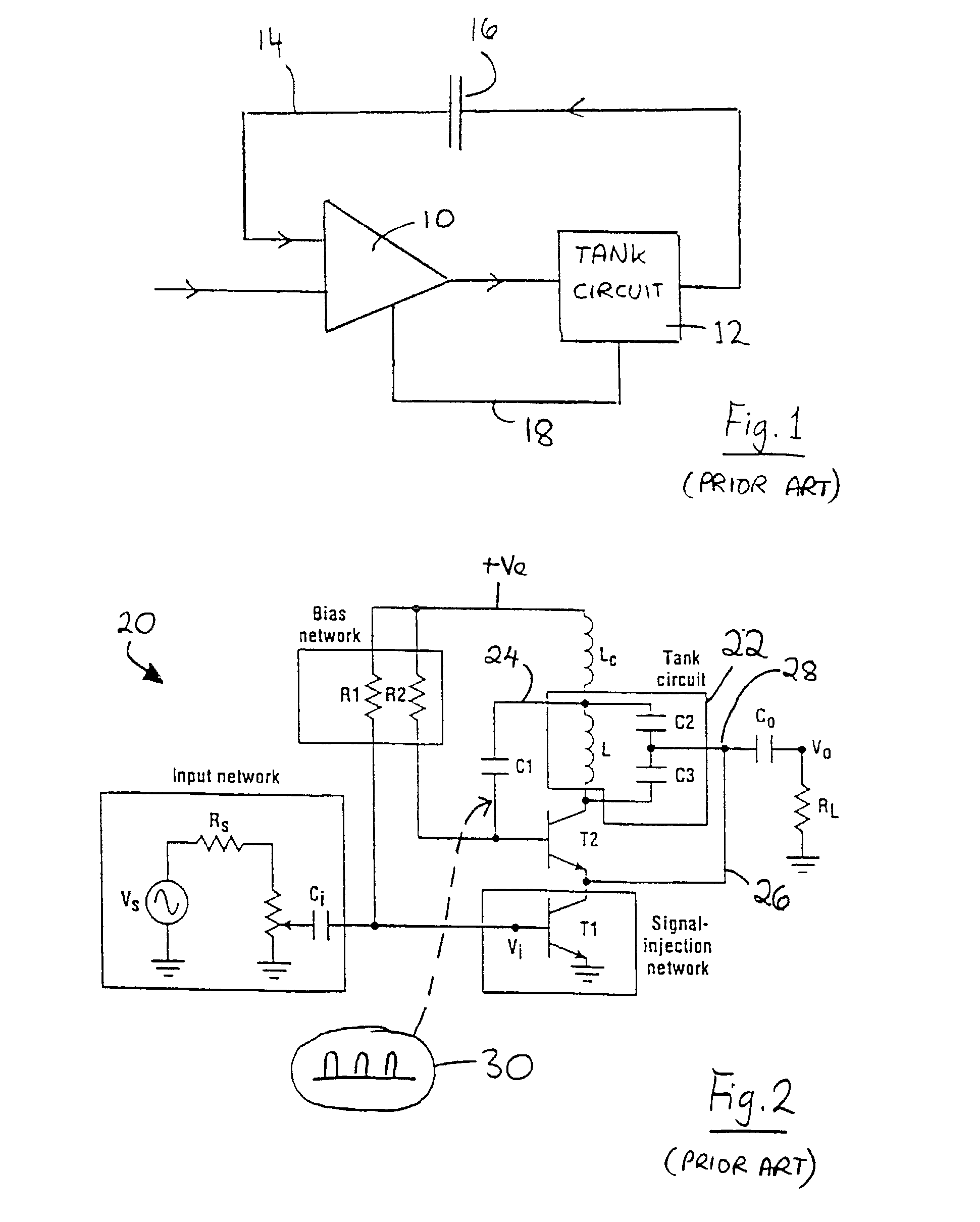
[0108] FIG. 7 illustrates the invention. This is similar to the synchronous oscillator shown in FIG. 2 (like numerals being used).

[0109] The circuit includes nodes 1, 2 and 3 of the oscillator transistor T2, and nodes 4, 5 and 6 of the tank circuit. Node 2 is coupled to node 5. The conventional first feedback path 24 is coupled between the input node 1 of the oscillator transistor T2 and node 4 of the tank circuit 22. The conventional second feedback path 26 is coupled between node 6 of the tank circuit 22 and node 3 of the oscillator transistor T2.

[0110] The present embodiment also comprises the third feedback path 40 coupled between node 5 of the tank circuit and node 1. The third feedback path 40 has a complex impedance and consists of a series coupled capacitor C4 and inductor L3 to provide the third feedback path 40 to the input (base) of the oscillator transistor T2. As mentioned, the third feedback path 40 originates from the collector of the oscillator transistor T2 and the ...

first embodiment

[0125] The circuit of FIG. 10 may provide the same performance enhancement as the preceding embodiment, namely an increase in bandwidth, improved input sensitivity, improved noise rejection, and a reduction in jitter. In the circuit of FIG. 10, frequency multiplication by a factor of three occurs (i.e. domination by the second harmonic), instead of times four as in the

[0126] The second embodiment is also suitable for use in QPSK modems. For example, a 48 MHz oscillator frequency can automatically be converted to around 140 MHz IF frequency.

[0127] In the first and second embodiments, the synchronous oscillators are not phase corrected. However, if desired, the same negative impedance conversion feedback may be used in a coherent phase synchronous oscillator. For example, FIG. 11 shows such a coherent phase oscillator similar to FIG. 5, with the addition of the third feedback path 40 employing the inductor L3 and the capacitor C4. Such a circuit may provide the same enhancement of per...


PUM


Abstract

A modification of the synchronous oscillator is described, having regenerative positive feedback. The circuit includes an amplifier, a high-Q tank circuit, and a conventional synchronous oscillator feedback network. An additional feedback path provides a negative impedance conversion effect.

Description

[0001] This is a continuation of UK application No. 0208034.9, filed on Apr. 8, 2002 and U.S. application Ser. No. 10 / 117,786, filed Apr. 5, 2002, which is a continuation of International Application PCT / IB00 / 01447, with an international filing date of Oct. 9, 2000 (09.10.2000), published in English under PCT Article 21(2) and now abandoned.[0002] This invention relates to the field of synchronous oscillators. Such oscillators are used as building blocks in a wide variety of circuit applications, including (but not limited to) clock recovery, modulation, encoding, decoding, signal detectors and discriminators, and direct sequence, spread spectrum (DSSS) systems. It is also ideal for broadband communications, in AM to FM conversion, FM to digital conversion, etc.BACKGROUND TO THE INVENTION[0003] The synchronous oscillator is well known, and is described, for example, in U.S. Pat. Nos. 4,274,067, 4,335,404 and 4,356,456 as well as in numerous papers published by the present inventor.[...

Claims


Application Information

Patent Timeline
Patent Type & Authority Applications(United States)
IPC IPC(8): H03B5/12H03L7/083H03L7/24H04L7/027
CPCH03L7/083H03L7/24H04L7/027H03B5/1231H03B5/1296H03B5/1203H03B2200/0074
Inventor UZUNOGLU, VASIL
Owner ANTHONY AESCHLIMANN
Why Eureka
Try Eureka