Apparatus and method for utilizing an actuator for flow control valve gates

Inactive Publication Date: 2003-01-16
SYNVENTIVE MOLDING SOLUTIONS INC
View PDF58 Cites 55 Cited by
  • Summary
  • Abstract
  • Description
  • Claims
  • Application Information

AI Technical Summary

Benefits of technology

0066] Another advantage of the present invention is seen in a multi-cavity system in which the nozzles are injecting into cavities which form different sized parts that require different fill rates and packing profiles. In this case, different pressure profiles can be programmed for each respective controller of each respective cavity. Still another advantage is when the size of the cavity is constantly changing, i.e., when making different size parts by changing a mold insert in which the part is formed. Rather than change the hardware (e.g., the nozzle) involved in order to change the fill rate and packing profile for the new part, a new program is chosen by the user corresponding to the new part to be formed.
0067] The embodiment of FIGS. 1 and 2 has the advantage of controlling the rate of melt flow away from the gate inside manifold 15 rather than at the gates 7 and 9. Controlling the melt flow away from the gate enables the pressure transducer to be located away from the gate (in FIGS. 1-5). In this way, the pressure transducer does not have to be placed inside the mold cavity, and is not susceptible to pressure spikes which can occur when the pressure transducer is located in the mold cavity or near the gate. Pressure spikes in the mold cavity result from the valve pin being closed at the gate. This pressure spike could cause an unintended response from the control system, for example, an opening of the valve pin to reduce the pressure--when the valve pin should be closed.
0068] Avoidance of the effects of a pressure spike resulting from closing the gate to the mold makes the control system behave more accurately and predictably. Controlling flow away from the gate enables accurate control using only a single sensed condition (e.g., pressure) as a variable. The '582 patent disclosed the use of two sensed conditions (valve position and pressure) to compensate for an unintended response from the pressure spike. Sensing two conditions resulted in a more complex control algorithm (which used two

Problems solved by technology

Placing the pressure transducer inside the mold cavity can result in the pressure transducer sensing pressure spikes which can occur when the valve pin is closed.
A

Method used


Image

  • Apparatus and method for utilizing an actuator for flow control valve gates
  • Apparatus and method for utilizing an actuator for flow control valve gates
  • Apparatus and method for utilizing an actuator for flow control valve gates

Examples


Embodiment Construction

[0004] 1. Field of the Invention

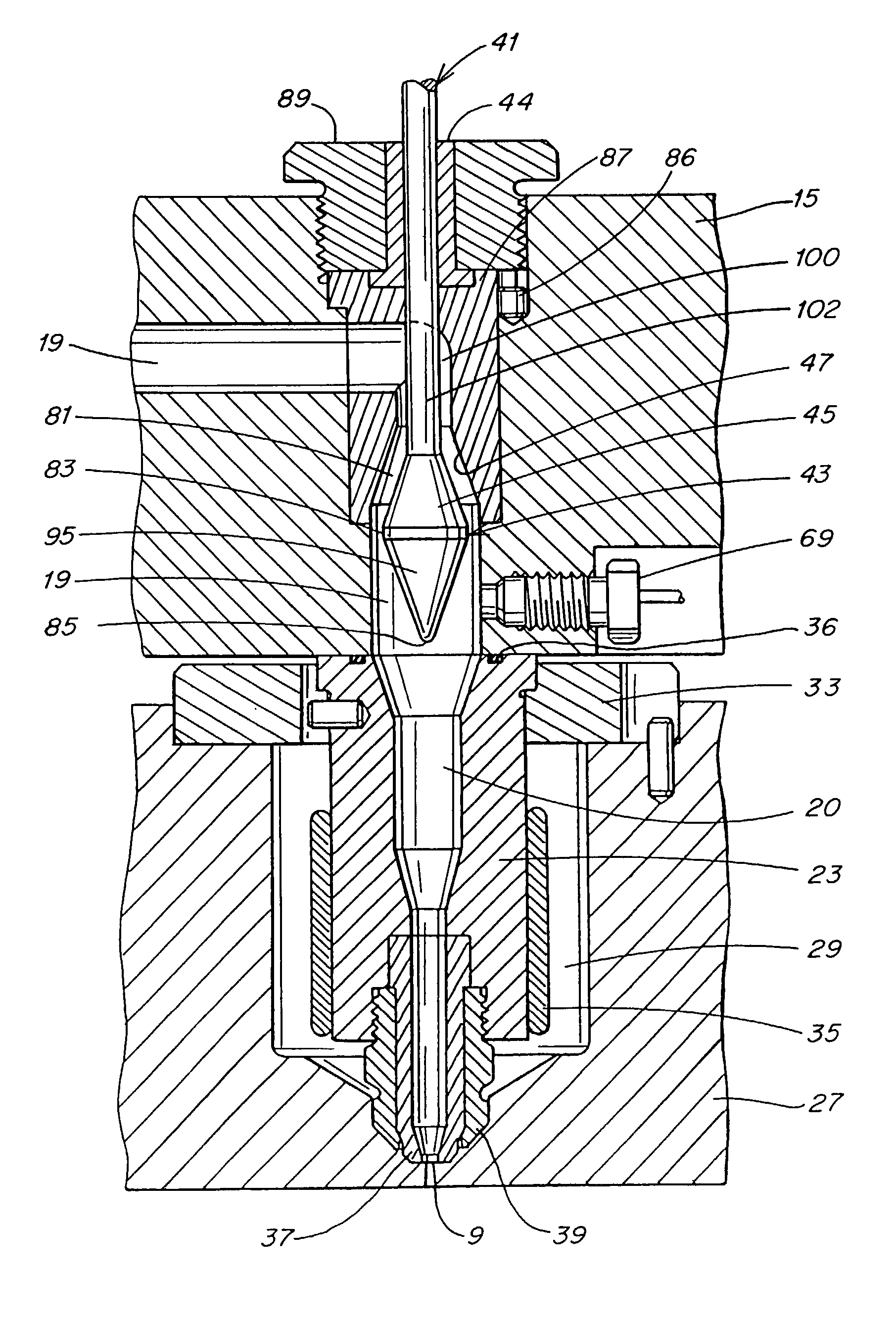
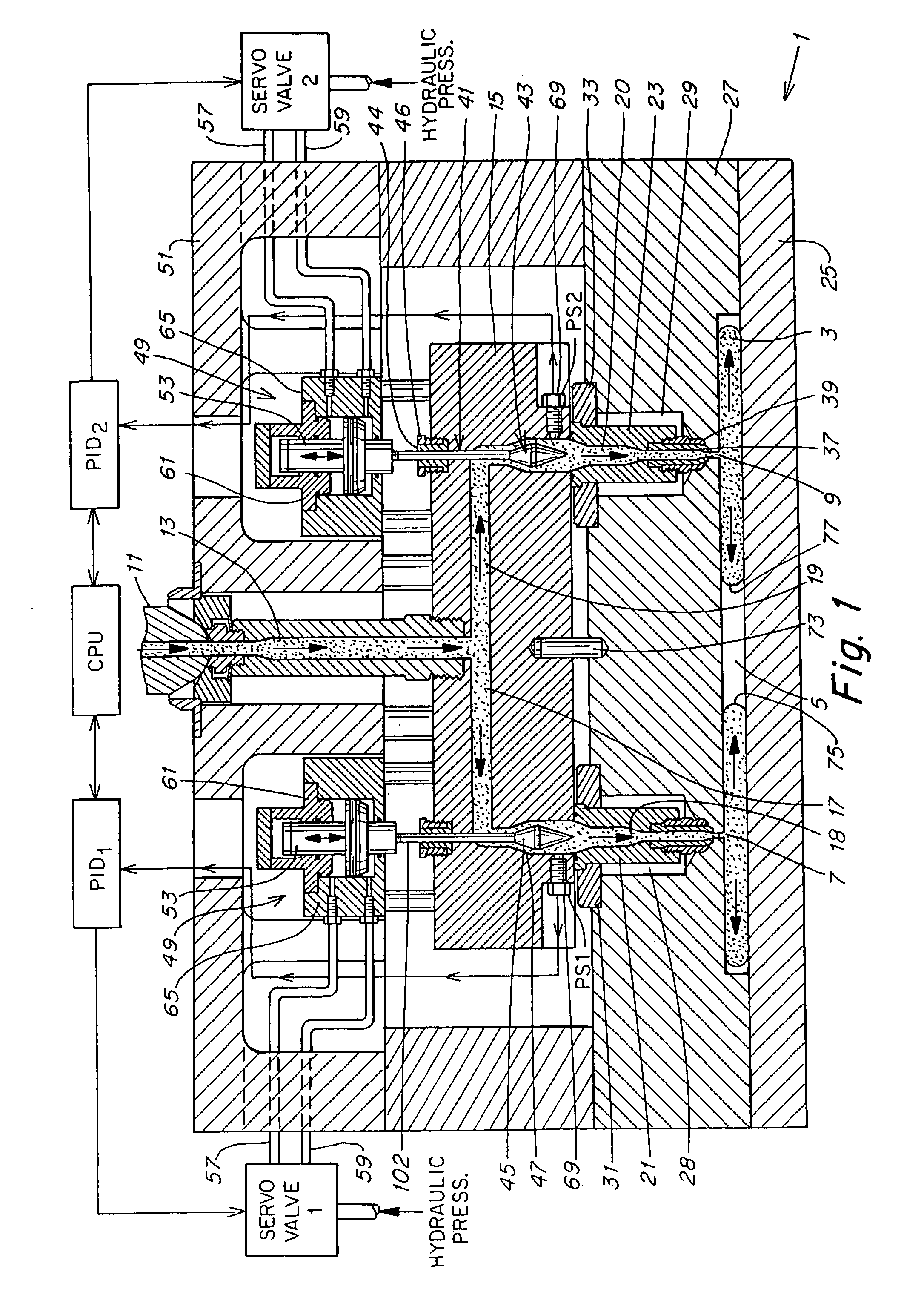
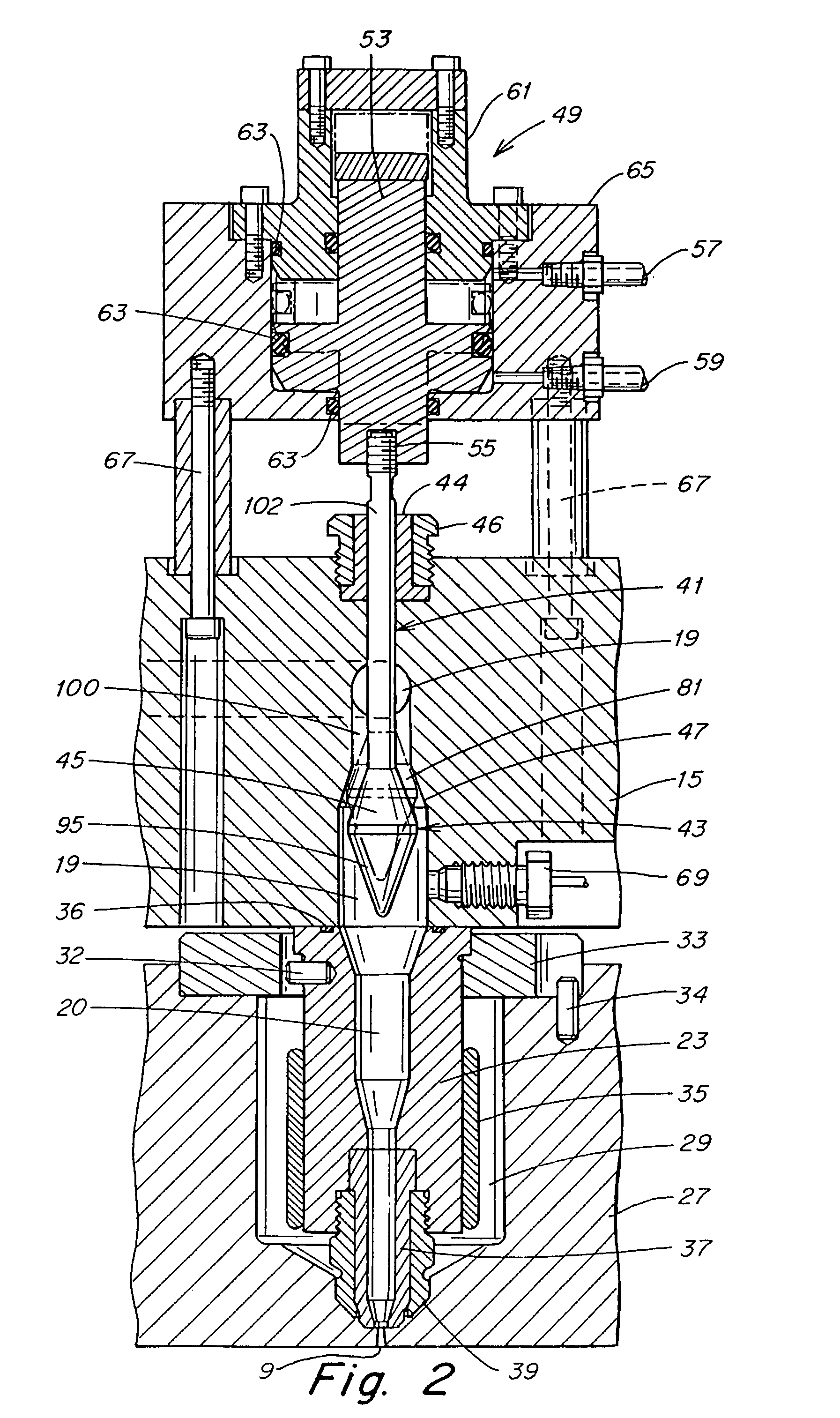
[0005] This invention relates to injection of pressurized materials through a distribution system, such as injection molding of plastic melt in a hot runner injection molding system. More specifically, this invention relates to an improved injection molding system in which the rate of material flow through two or more gates is independently controlled.

[0006] 2. Description of the Related Art

[0007] U.S. Pat. No. 5,556,582 discloses a multi-gate single cavity system in which the rate of melt flow through the individual gates is controlled independently via a control system according to specific target process conditions.

[0008] This system enables the weld line of the part (the section of the part in which the melt from one gate meets the melt from another gate) to be selectively located. It also enables the shape of the weld line to be altered to form a stronger bond.

[0009] The '582 patent discloses controlling the rate of melt flow with a tapered valve...


PUM

PropertyMeasurementUnit
Flow rateaaaaaaaaaa

Abstract

Injection molding apparati, systems and methods are provided for limiting forward valve pin movement during flow control. According to one embodiment, an injection molding apparatus is provided that includes an actuator, and a valve pin coupled to the actuator. The valve pin is adapted to open and close a gate to a mold, and to control a rate of material flow through the gate during an injection cycle. The actuator is further adapted to control the valve pin in a first range of movement in which the valve pin is adapted to control the rate of material flow and cannot close the gate, and to control the valve pin in a second range of movement which includes the valve pin closing the gate.

Description

[0001] This application is a continuation-in-part under 35 U.S.C. .sctn.120 of U.S. application Ser. No. 09 / 699,856, entitled "CONTROLLED INJECTION USING MANIFOLD HAVING MULTIPLE FEED CHANNELS", filed Oct. 30, 2000, which is a continuation-in-part of U.S. application Ser. No. 09 / 503,832, entitled DYNAMIC FEED CONTROL SYSTEM, filed Feb. 15, 2000, which is a continuation-in-part of U.S. application Ser. No. 09 / 400,533, entitled "MANIFOLD SYSTEM HAVING FLOW CONTROL", filed Sep. 21, 1999, which is a continuation-in-part of U.S. application Ser. No. 09 / 063,762, entitled "MANIFOLD SYSTEM HAVING FLOW CONTROL", filed Apr. 21, 1998.[0002] This application is also a continuation-in-part under 35 U.S.C. .sctn.120 of U.S. application Ser. No. 09 / 503,832, listed above. This application is also a continuation-in-part of U.S. application Ser. No. 09 / 400,533, listed above. This application also claims priority under 35 U.S.C. .sctn.119(e) to provisional application serial No. 60 / 299,697, filed Jun....

Claims


Application Information

Patent Timeline
IPC IPC(8): B29C45/27B29C45/28B29C45/30B29C45/32B29C45/76B29C45/77
CPCB29C45/27B29C45/2701B29C45/2704B29C45/2806B29C45/281B29C45/30B29C45/322B29C45/76B29C45/77B29C2045/2687B29C2045/2722B29C2045/2761B29C2045/279B29C2045/2817B29C2045/2855B29C2045/2872B29C2045/2882B29C2045/2886B29C2045/304B29C2045/306B29C2945/76006B29C2945/76277B29C2945/76381B29C2945/76498B29C2945/76568B29C2945/76755B29C2945/76859
Inventor DOYLE, MARKKAZMER, DAVIDMOSS, MARKGALATI, VITO
Owner SYNVENTIVE MOLDING SOLUTIONS INC
Why Eureka
Try Eureka