
Method and system for reducing dn/dt birefringence in a thermo-optic PLC device

a technology of thermo-optic plc and birefringence, applied in the field of method and system, can solve the problems of polarization sensitivity, polarization sensitivity is a problem, and polarization sensitivity is even more problematic, and achieve the effect of increasing dopant concentration and expanding rapidly

Inactive Publication Date: 2003-02-13
NEOPHOTONICS CORP
View PDF0 Cites 32 Cited by
  • Summary
  • Abstract
  • Description
  • Claims
  • Application Information

AI Technical Summary

Benefits of technology

[0013] The present invention is a method and system for reducing dn / dt birefringence in a thermo-optic PLC device. The present invention provides a solution that matches the TE and TM propagation modes of an optical signal within active PLC devices. The present invention minimizes thermally induced dn / dt birefringence within thermo-optic PLC devices. Additionally, the present invention does not add additional film deposition steps to the PLC device fabrication process.
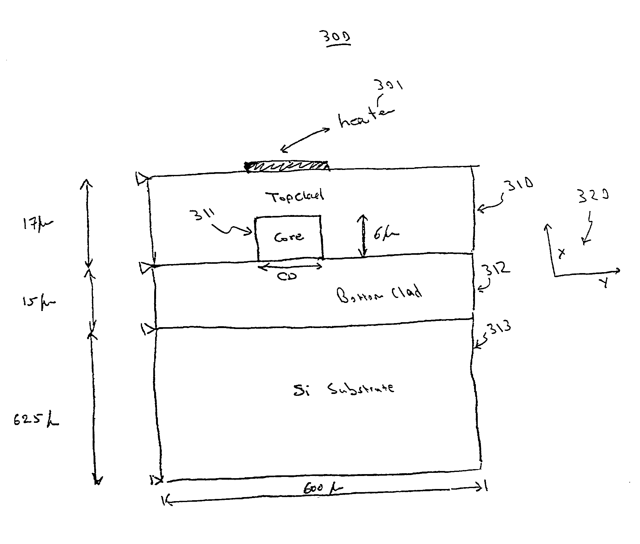
[0014] In one embodiment, the present invention is implemented as a PLC device fabrication process for making optical waveguide structures for thermo-optic PLC devices having a reduced dn / dt birefringence. The process includes the step of forming a waveguide core layer on a bottom cladding, the waveguide core layer having a higher refractive index than the bottom cladding. The waveguide core layer is then etched to define a waveguide core. A top cladding is subsequently formed over the waveguide core and the bottom cladding. The top cladding also has a lower refractive index than the waveguide core. The top cladding is then etched to define a first trench and a second trench parallel to the waveguide core. The first trench and the second trench are configured to relieve a stress on the waveguide core. This stress can be induced by a heater, as in a case where the active PLC is a thermo-optic PLC.
[0016] The first trench and the second trench are configured to balance a stress within the waveguide core. Both tensile stresses and compressive stresses exist within the waveguide structure due to the thermal expansion characteristics of the top and bottom cladding and the waveguide core. The first and second trenches balance the stresses by allowing the top cladding to more readily expand. A cap can be formed over the waveguide core prior to forming the top cladding to further balance the stress within the waveguide core. Additionally, the bottom cladding can have a higher dopant concentration than the top cladding to further balance the tensile stress within the waveguide core.

Problems solved by technology

A well-known problem with many PLCs is the polarization sensitivity of the device.
Polarization sensitivity is a problem for both active PLC devices and passive PLC devices.
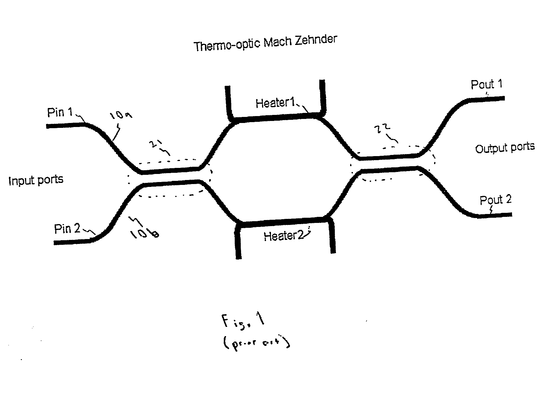
Polarization sensitivity is even more problematic with active PLC devices, particularly thermo-optic PLC devices where thermally induced birefringence exists in addition to any "intrinsic" birefringence of the PLC waveguides.
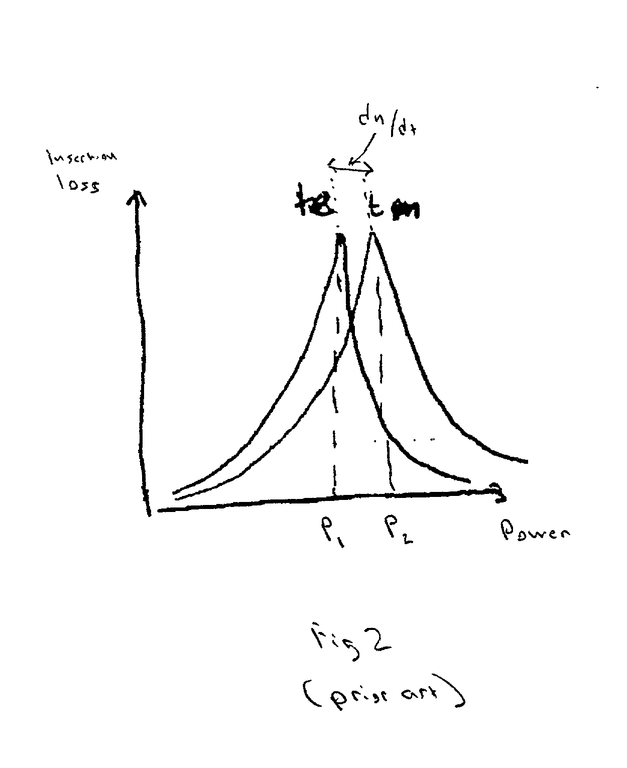
There exists a problem, however, in that the thermal stress-induced polarization sensitivity causes birefringence problems within the devices.
This mismatch can cause a polarization dependent loss, wherein either the TE or TM mode is attenuated within the optical waveguide structures to a greater degree than the other, and other types of problems.

Method used


Image

  • Method and system for reducing dn/dt birefringence in a thermo-optic PLC device
  • Method and system for reducing dn/dt birefringence in a thermo-optic PLC device
  • Method and system for reducing dn/dt birefringence in a thermo-optic PLC device

Examples


Embodiment Construction

[0028] Reference will now be made in detail to the embodiments of the invention, examples of which are illustrated in the accompanying drawings. While the invention will be described in conjunction with the preferred embodiments, it will be understood that they are not intended to limit the invention to these embodiments. On the contrary, the invention is intended to cover alternatives, modifications and equivalents, which may be included within the spirit and scope of the invention as defined by the appended claims. Furthermore, in the following detailed description of the present invention, numerous specific details are set forth in order to provide a thorough understanding of the present invention. However, it will be obvious to one of ordinary skill in the art that the present invention may be practiced without these specific details. In other instances, well known methods, procedures, components, and circuits have not been described in detail as not to obscure aspects of the pr...


PUM


Abstract

A method of making an optical waveguide structure for an active PLC device having a reduced dn / dt birefringence. The method includes the step of forming a waveguide core layer on a bottom cladding, the waveguide core layer having a higher refractive index than the bottom cladding. The waveguide core layer is then etched to define a waveguide core. A top cladding is subsequently formed over the waveguide core and the bottom cladding. The top cladding also has a lower refractive index than the waveguide core. The top cladding is then etched to define a first trench and a second trench parallel to the waveguide core. The first trench and the second trench are configured to relieve a stress on the waveguide core. This stress can be induced by a heater, as in a case where the active PLC is a thermo-optic PLC. The first trench and the second trench can extend from an upper surface of the top cladding to an upper surface of the bottom cladding. The first trench and the second trench can extend from the upper surface of the top cladding into a portion of the underlying substrate. The first trench and the second trench are configured to balance a tensile stress within the waveguide core. A cap can be formed over the waveguide core prior to forming the top cladding to further balance the tensile stress within the waveguide core. The bottom cladding can have a higher dopant concentration than the top cladding.

Description

FIELD OF THE INVENTION[0001] The present invention relates generally to planar lightwave circuits. More particularly, the present invention relates to a method and system for a reduced polarization dependent wavelength shift / polarization dependent loss of planar lightwave circuit.BACKGROUND OF THE INVENTION[0002] Planar lightwave circuits comprise fundamental building blocks for the newly emerging, modern fiberoptic communications infrastructure. Planar lightwave circuits are innovative devices configured to transmit light in a manner analogous to the transmission of electrical currents in printed circuit boards and integrated circuit devices. Examples include arrayed waveguide grating devices, integrated wavelength multiplexers / demultiplexers, optical switches, optical modulators, wavelength-independent optical couplers, and the like.[0003] Planar lightwave circuits (PLCs) generally involve the provisioning of a series of embedded optical waveguides upon a semiconductor substrate (...

Claims


Application Information

Patent Timeline
IPC IPC(8): G02F1/01G02F1/313
CPCG02F1/0147G02F2001/0113G02F1/3136G02F1/0113
Inventor PARHAMI, FARNAZLIU, ALICETRAMMEL, PAMELA S.
Owner NEOPHOTONICS CORP
Learn More