Turbogroup of a power generating plant

a technology of power generating plant and turbine unit, which is applied in the direction of machines/engines, machine supports, liquid fuel engines, etc., can solve the problems of friction, heat generation, wear, and increase in the outer casing temperature of the turbine unit from top to bottom, and cannot be ruled ou

Inactive Publication Date: 2003-02-20
ALSTOM TECH LTD
View PDF0 Cites 13 Cited by
  • Summary
  • Abstract
  • Description
  • Claims
  • Application Information

AI Technical Summary

Benefits of technology

[0010] In addition, the proposed type of construction makes it possible for the turbine unit to be compact in the axial direction, since the bearing system in the region of the second radial bearing unit is of markedly smaller construction than in conventional turbogroups. Furthermore, the oil supply and the instrumentation for the thrust bearing unit are simplified, since the latter, according to the invention, is not accommodated in the casing of the further fluid-flow machine or in the casing of the turbine unit but outside it.

Problems solved by technology

Thrust bearings react in a sensitive manner to changes in inclination and misalignments; in particular, friction, the generation of heat, and wear increase.
However, if a combustion chamber lying at the top, a "silo combustion chamber", is used instead of an annular combustion chamber, temperature differences in the outer casing of the turbine unit from top to bottom cannot be ruled out.
Since the thrust bearing unit is normally integrated in the casing of the turbine unit next to the second radial bearing unit, the relative position between the bearing axis of the bearing unit fixed to the casing and the rotation axis of the turbine shaft may change to a relatively pronounced degree due to the asymmetrical thermal expansion of the casing, as a result of which a proper thrust bearing arrangement is put at risk.
This may also intensify the thermal expansion effects.
On account of the highly complex coupling of the vibration systems and on account of a multiplicity of boundary conditions which cannot be determined exactly, it is presently not possible to be able to predict the vibration behavior of the turbine unit and of the associated bearing system in a sufficiently reliable manner at a justifiable cost.

Method used


Image

  • Turbogroup of a power generating plant
  • Turbogroup of a power generating plant
  • Turbogroup of a power generating plant

Examples


Embodiment Construction

[0007] The invention is intended to provide a remedy here. The invention, as characterized in the claims, deals with the problem of showing how, for a turbogroup of the type mentioned at the beginning, to make it possible or easier to influence the vibration behavior of the turbine unit and / or of the bearing system.

[0008] This problem is achieved according to the invention by the subject matter of the independent claim. Advantageous embodiments are the subject matter of the dependent claims.

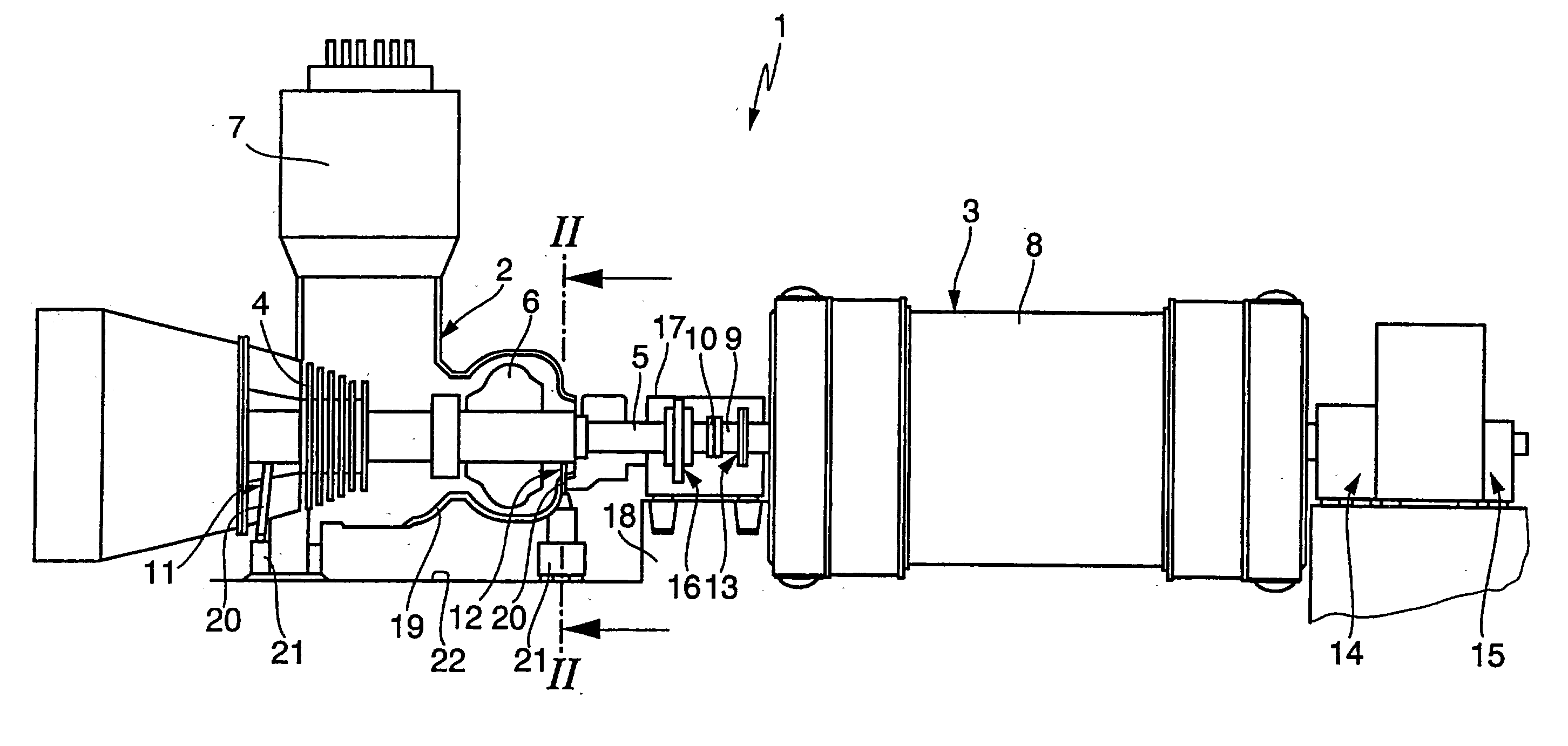
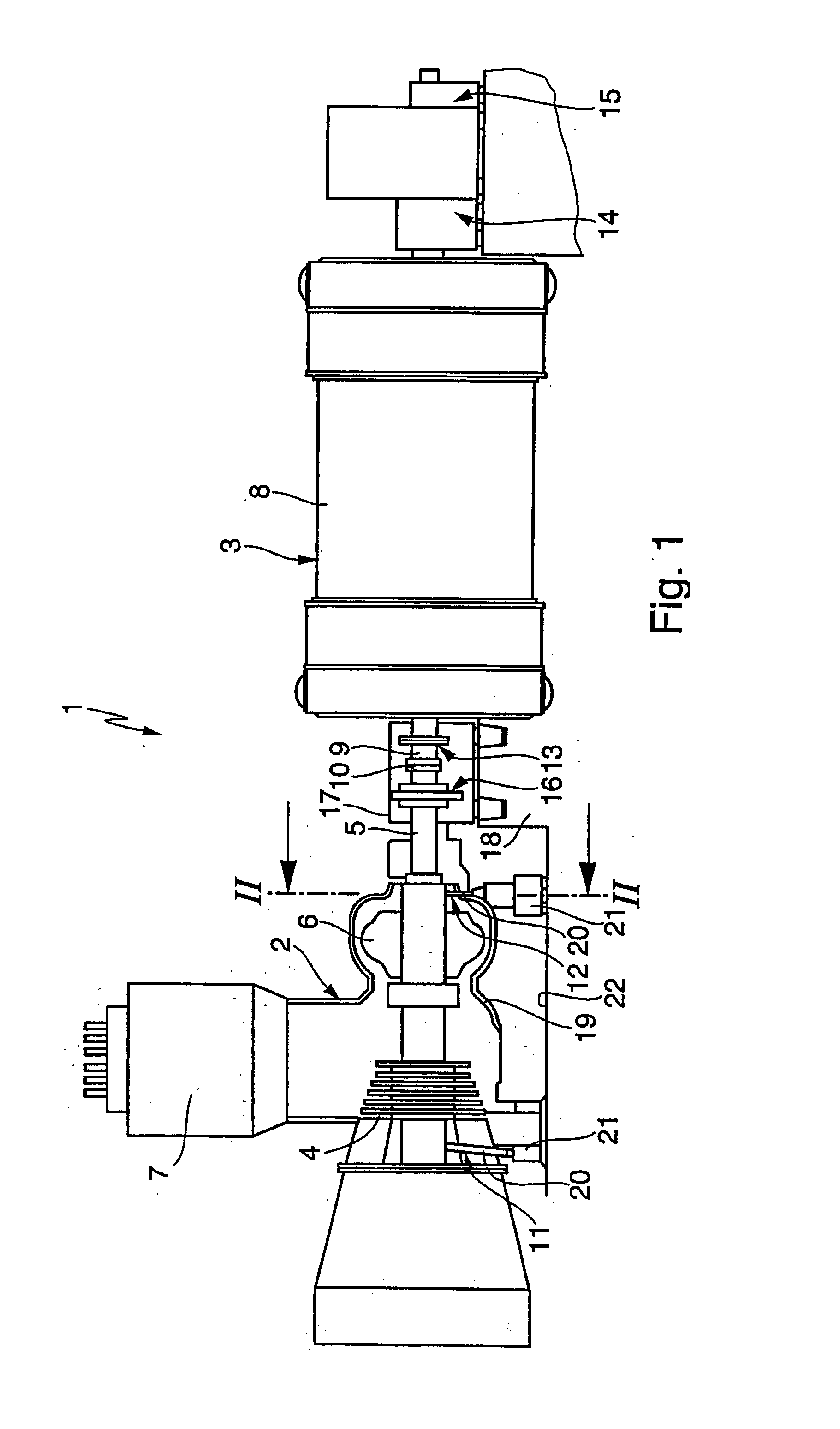
[0009] The present invention is based on the general idea of integrating the thrust bearing unit together with the third radial bearing unit in a common bearing block, this common bearing block being firmly attached to a foundation. Due to this measure, the axial support of the turbine shaft is effected in the region of the third radial bearing unit, which is actually assigned to the generator. This means that, in this type of construction, the axial support of the turbine shaft is separated from...


PUM


Abstract

The present invention relates to a turbogroup (1) of a power generating plant. A turbine unit (2), has a turbine (4) and a further fluid-flow machine (6) on a common turbine shaft. A generator unit (3), has a generator (8) on a generator shaft (9). The turbine shaft (5) and the generator shaft (9) are connected to one another. A third radial bearing unit (13) supports the generator shaft (9) on a side of the generator (8) which faces the turbine unit (2). A thrust bearing unit (16) supports the turbine shaft (5) axially between the generator (8) and the additional fluid-flow machine (6). The thrust bearing unit (16) and the third radial bearing unit (13) are integrated in a common bearing block (17) which is firmly connected to a fixed foundation (18).

Description

[0001] The invention relates to a turbogroup of a power generating plant, in particular a gas-storage power plant, comprising a turbine unit and a generator unit.PRIOR ART[0002] A turbine unit normally has a turbine and a further fluid-flow machine on a common turbine shaft. In a conventional power generating plant, this further fluid-flow machine may be formed by a compressor which is driven by the turbine via the turbine shaft. In a gas-storage power plant, in particular an air-storage power plant, this further fluid-flow machine is formed by an additional turbine, to which the gas of a gas reservoir of the gas-storage power plant is admitted, so that the additional turbine likewise transmits drive output to the turbine shaft. As a rule, a generator unit has a rotor of a generator on a generator shaft and serves to generate electricity. The turbine unit serves to drive the generator unit, so that accordingly the turbine shaft is in drive connection with the generator shaft.[0003] ...

Claims


Application Information

Patent Timeline
Patent Type & Authority Applications(United States)
IPC IPC(8): F01D25/16
CPCF01D25/164
Inventor HUSTER, JOSEFKELLER, SUSANNELOBMUELLER, WALTER
Owner ALSTOM TECH LTD
Why Eureka
Try Eureka